Medical Instrument

a technology for medical instruments and rotating parts, applied in the field of medical instruments, can solve the problems of difficult handling of medical instruments in order to perform such a rotation movement and the relatively narrow angle range available, and achieve the effect of improving the handling of medical instruments

Active Publication Date: 2014-10-23
KARL STORZ GMBH & CO KG
View PDF6 Cites 36 Cited by
  • Summary
  • Abstract
  • Description
  • Claims
  • Application Information

AI Technical Summary

Benefits of technology

[0004]It is an object of the present invention to improve the handling of a medical instrument...

Problems solved by technology

However, since the proximal end area of the instrument lies closely on the scalp, the handling of the instrument in or...

Method used


Image

  • Medical Instrument
  • Medical Instrument
  • Medical Instrument

Examples


Embodiment Construction

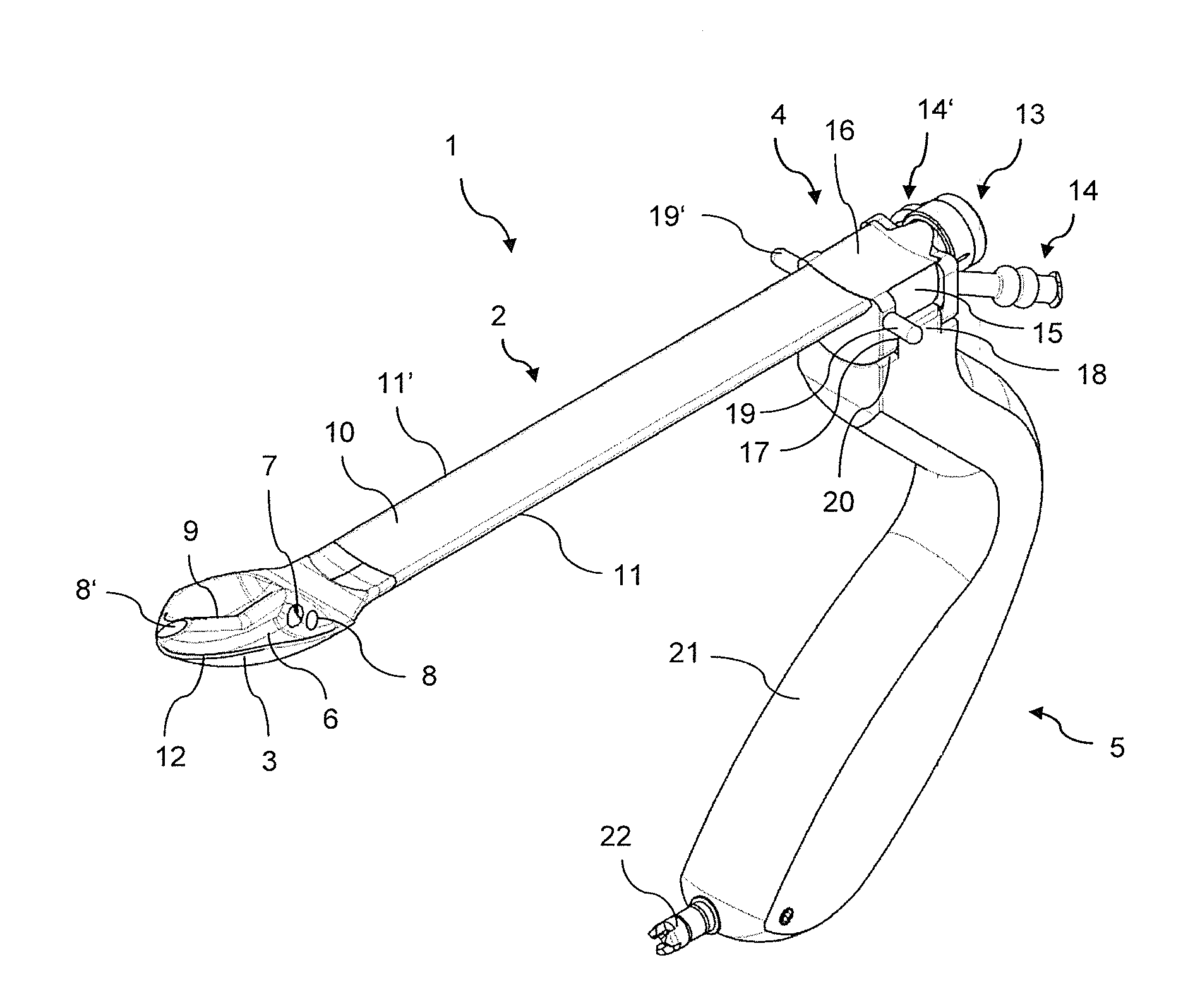
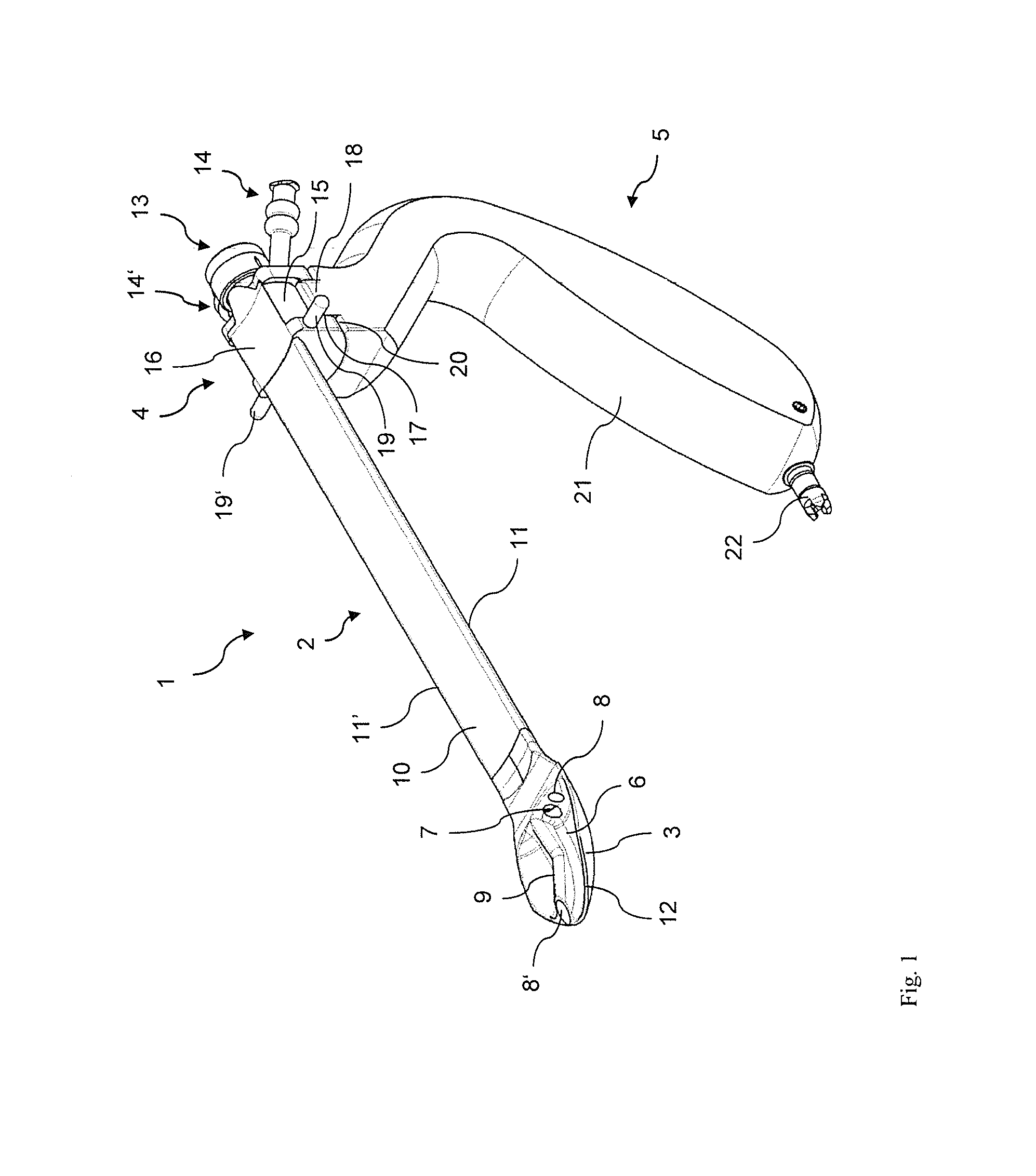
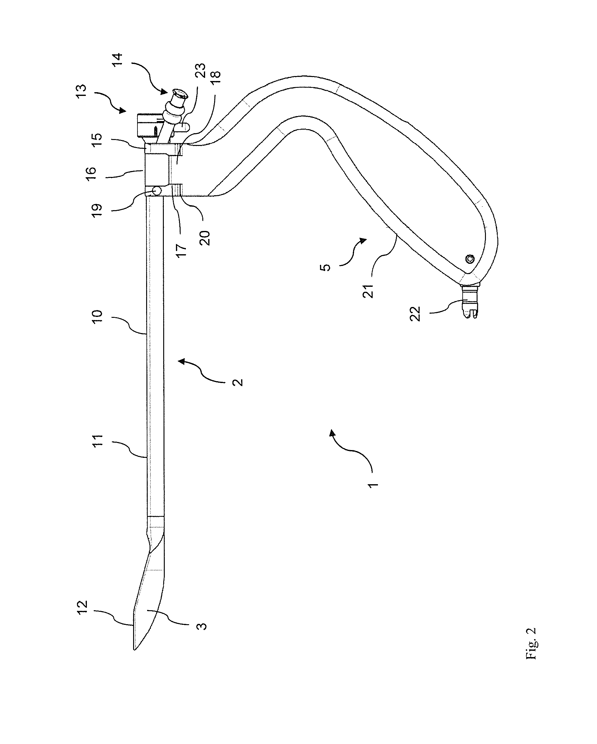
[0029]The medical instrument 1 shown in a perspective view in FIG. 1 comprises an elongate shank 2 which, at its distal end, has a spoon-shaped spatula 3, and, at its proximal end, has a shank head 4 on which a handle 5 is mounted. The spatula 3 is oriented more or less in a continuation of the shank 2 but is slightly angled in the direction away from the handle 5, i.e. upward in the view shown in FIG. 1. In its interior, the spoon-shaped spatula 3 forms a hollow space 6. An optics channel 7 and a first rinsing / suctioning channel 8 open into the hollow space 6. A further rinsing / suctioning channel 8′ is routed via an angled tube 9 through the hollow space 6 and opens out in the distal end area of the spatula 3. The shank 2 has a shallow kidney-shaped cross section and has a shallow trough-shaped top face 10. The edges 11, 11′ of the shank 2 and the edge 12 of the spatula 3 are rounded to avoid causing trauma.

[0030]An endoscope lens system, which is not shown in FIG. 1, can be in...


PUM


Abstract

A medical instrument with an elongate shank which, at a distal end, carries a spatula, and, in a proximal end area, has a shank head on which a laterally protruding handle is arranged. The shank is rotatable relative to the handle about a rotation axis parallel to a longitudinal axis of the shank.

Description

FIELD OF THE INVENTION[0001]The present invention relates to a medical instrument with an elongate shank which, at a distal end, carries a spatula, and, in a proximal area, has a shank head on which a laterally protruding handle is arranged.BACKGROUND OF THE INVENTION[0002]The laid-open application DE 198 27 360 A1 discloses a medical instrument with an elongate shank which, at the distal end, has a spatula tip, and in the proximal area of which a laterally projecting handle is arranged. The handle is connected to the shank in such a way that an outer face of the instrument directed away from the handle has a substantially uniform surface extending continuously from the distal to the proximal end. The known instrument also has an endoscope lens system with an eyepiece inclined, substantially on the same side as the handle, in relation to a longitudinal central axis of the shank. The known medical instrument is intended for endoscopic removal of the vena saphena magna, wherein the in...

Claims


Application Information

Patent Timeline
IPC IPC(8): A61B17/02
CPCA61B17/02A61B1/00128A61B1/313A61B17/00008A61B2017/0046A61B2017/00477A61B2017/291A61B1/00135A61B2090/0817
Inventor HERMLE, RAINER
Owner KARL STORZ GMBH & CO KG
Why Eureka
Try Eureka