Electric machine

Active Publication Date: 2014-10-30
DIEN GHING HSIN
View PDF10 Cites 5 Cited by
  • Summary
  • Abstract
  • Description
  • Claims
  • Application Information

AI Technical Summary

Benefits of technology

[0014]As mentioned above, the electric machine of the invention has a novel design or arrangement of the stator units, there

Problems solved by technology

However, this kind of electric machine has some drawbacks.
For example, most coils can not be wound inside the stator slots in advance, so that the manufacturing speed can not be improved and the production cost can not be reduced.
Moreover, the conventional design of the stator slots provides a gap between the teeth for winding coils during the manufacturing process.
These gaps will cause the cogging torque as the rotor rotates, which results in the unsmooth rotation of the rotor.
The cogging torque may cause some drawbacks such as the unsmooth operation of the motor, back EMF, noise (due to teeth vibration), lower torque output, and the likes.
Moreover, in the generator application, the cogging torque will cause a re

Method used


Image

  • Electric machine
  • Electric machine
  • Electric machine

Examples


first embodiment

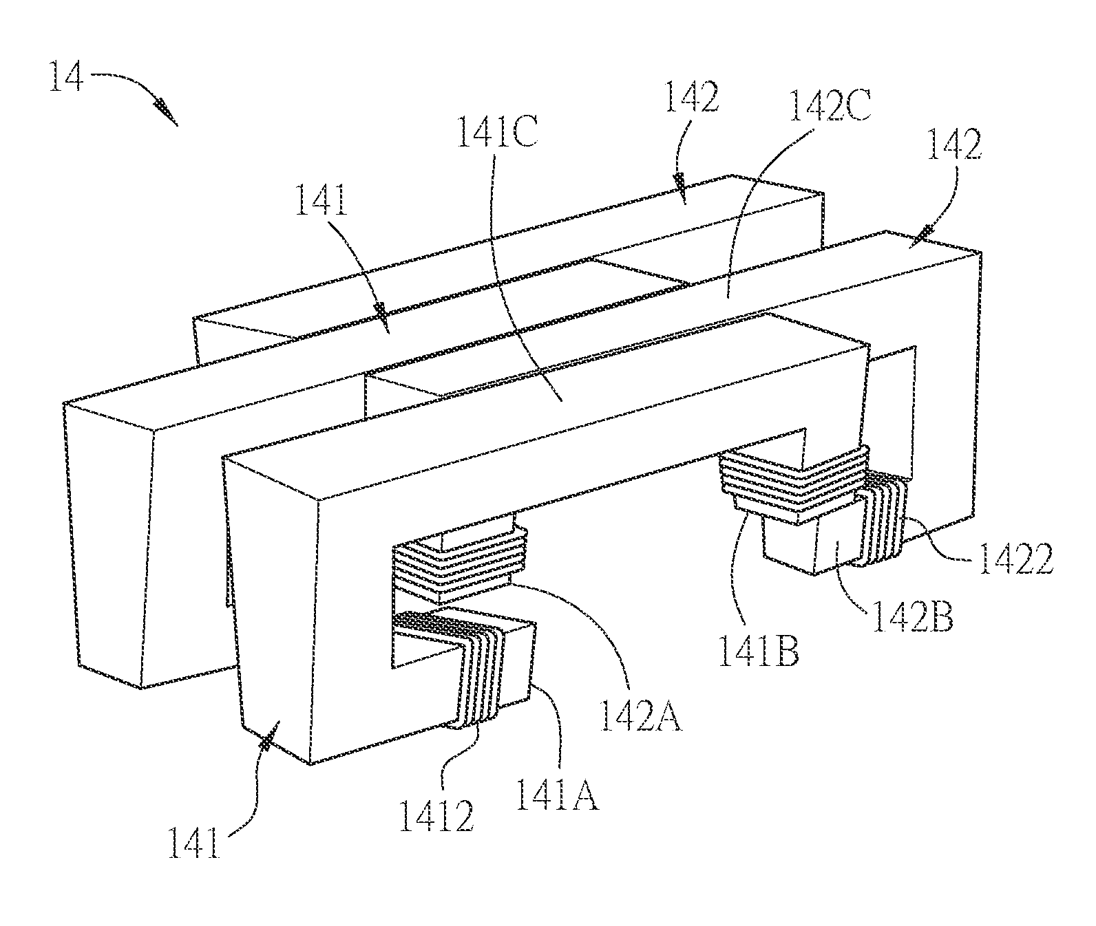
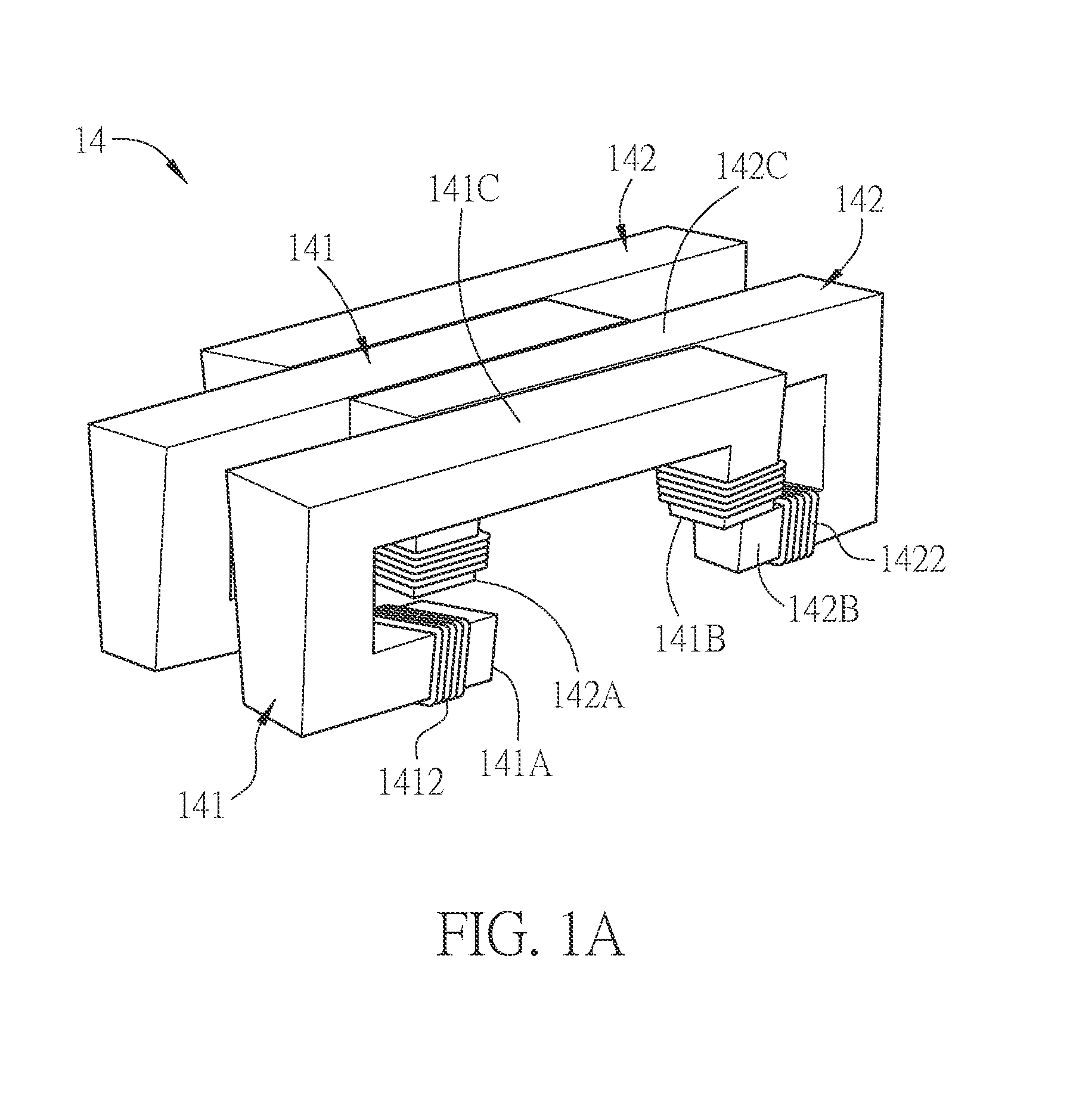
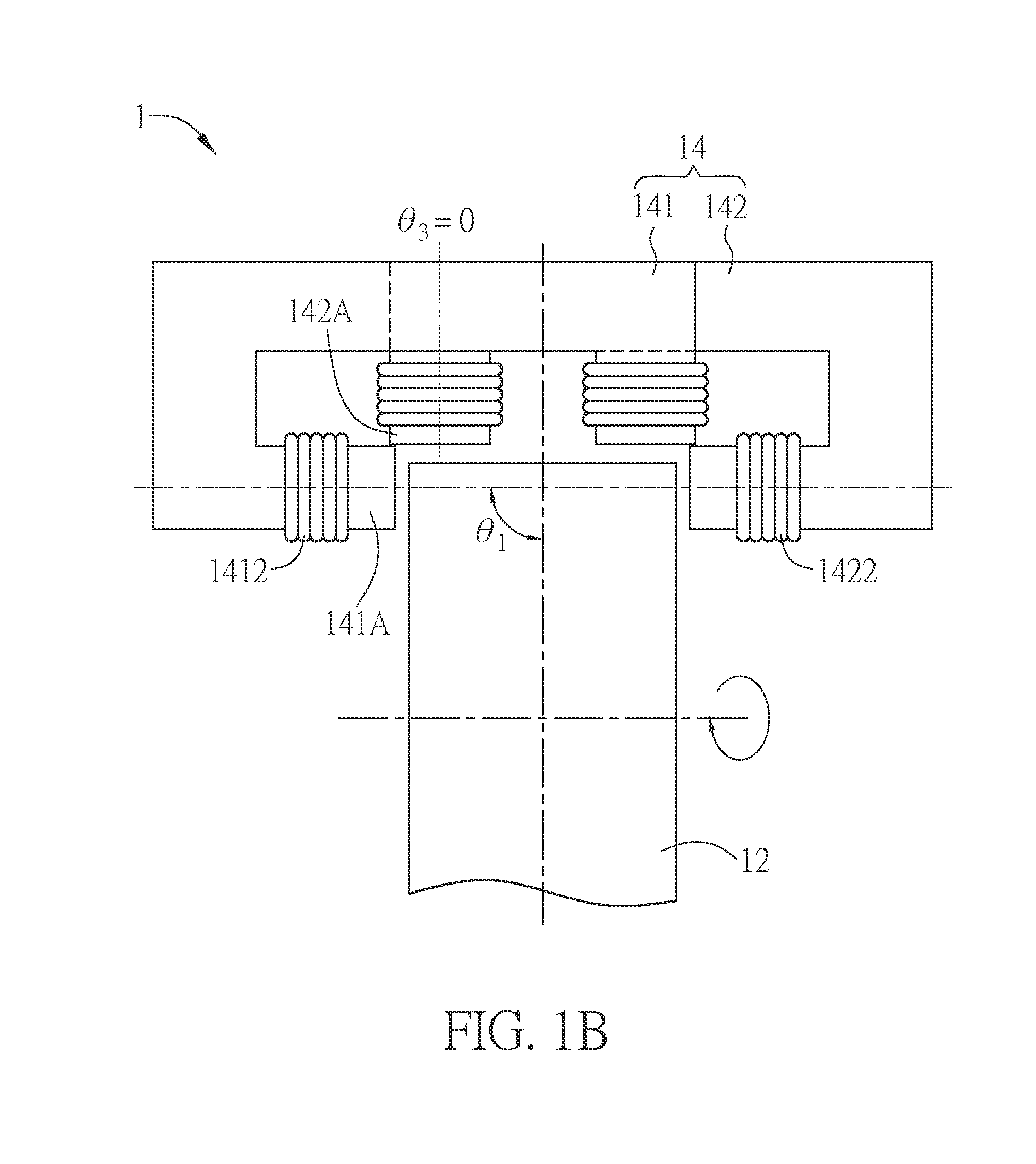
[0045]FIGS. 1A to 1C are schematic diagrams, a front view and a side view of a stator according to the invention.

[0046]Referring to FIGS. 1A to 1C, an electric machine 1 according to a first embodiment of the invention includes a rotor 12 and a stator 14. The stator 14 is disposed near to the rotor 12, and includes at least a first stator unit 141 and at least a second stator unit 142, and the stator units are adjacently disposed or adjacently arranged. For the sake of easy description, the figures only show two first stator units 141 and two second stator units 142, and the magnets inside the rotor 12 are omitted. The first stator unit 141 and the second stator unit 142 are alternately arranged or misaligned. Besides, the first stator unit 141 and the adjacent second stator unit 142 are tightly placed together and substantially have no gap therebetween.

[0047]To be noted, the term “adjacently disposed” or “adjacently arranged” means that the stator units 141 and 142 are disposed alo...

second embodiment

[0060]FIG. 2A is a schematic diagram showing a stator 24 according to the invention, and FIG. 2B is a front view of the stator 24 of FIG. 2A in cooperate with a rotor 22. For the sake of clear illustration, the coils 2412 and 2422 of the first stator unit 241 and the second stator unit 242 are omitted in FIG. 2A, and the winding methods thereof can be referred to FIG. 2B. FIG. 2B also shows a magnet (not labeled) embedded in the rotor 22, so that it will not be detached from the rotor 22 in high-speed rotation and can provide a uniform magnetic force for operation.

[0061]Different from the first embodiment, the front ends of the teeth of the first stator units 241 and the second stator units 242 of the stator 24 have slanted surfaces. In other words, the front ends of the first tooth 241A of the first stator unit 241 and the third tooth 242A of the second stator unit 242, which are adjacently disposed, substantially align to a coplanar surface, thereby forming a substantially continu...

third embodiment

[0064]FIG. 3A is a schematic diagram showing a stator 34 according to the invention, and FIG. 3B is a front view of the stator 34 of FIG. 3A. To be noted, for clearly illustrating the third angle θ3, the second stator unit 342 is shown in the front in FIG. 3B, and the relative position between the first stator unit 341 and the second stator unit 342 is still the same.

[0065]Different from the second embodiment, the protruding directions of the front ends of the first tooth 341A of the first stator unit 341 and the third tooth 342A of the second stator unit 342 are the same. In the third embodiment, a protruding length L1 of the first tooth 341A of the first stator unit 341 is different from the protruding length L2 of the third tooth 342A of the second stator unit 342. In other words, the front ends of the first tooth 341A and the third tooth 342A have the same included angle (90 degrees) with the radial direction of the rotor (not shown), but the protruding lengths of the front edge...


PUM


Abstract

An electric machine includes a stator and a rotor. The stator is disposed near to the rotor and has at least one first stator unit and at least one second stator unit. The first stator unit has a first tooth and a second tooth, and the second stator unit has a third tooth and a fourth tooth. The rotor has a rotating direction or a moving direction with respect to the stator. The first tooth and the third tooth are adjacently disposed to each other along the rotating direction or the moving direction. The protruding directions of the first tooth and the third tooth respectively form a first angle and a third angle with the radial direction of the rotor, and the first angle and the third angle are different.

Description

CROSS REFERENCE TO RELATED APPLICATIONS[0001]This Non-provisional application claims priority under 35 U.S.C. §119(a) on Patent Application No(s). 102115499 filed in Taiwan, Republic of China on Apr. 30, 2013, the entire contents of which are hereby incorporated by reference.BACKGROUND OF THE INVENTION[0002]1. Field of Invention[0003]The present invention relates to an electric machine.[0004]2. Related Art[0005]The electric machine is the most commonly used driving device. According to the functions, the electric machine can be divided into the motor and generator. In particular, the motor can convert the electric or magnetic power into mechanical power, and it has been widely applied to the machines of various fields.[0006]In general, the motor includes a rotor and a stator, and the rotor can be driven to rotate by the magnetic flux between the stator and rotor so as to generate the required mechanical energy. In order to provide the path for magnetic flux, the conventional motor i...

Claims


Application Information

Patent Timeline
IPC IPC(8): H02K1/16
CPCH02K1/16H02K19/103H02K21/12H02K2201/12
Inventor DIEN, GHING-HSIN
Owner DIEN GHING HSIN
Why Eureka
Try Eureka