Motor with simplified structure and related control device

a technology of motors and control devices, applied in the direction of windings, salient poles, magnetic circuit shapes/forms/construction, etc., can solve the problems of low efficiency of winding motor windings, and difficulty in miniaturizing motors at low cos

Inactive Publication Date: 2010-11-02
DENSO CORP
View PDF8 Cites 2 Cited by
  • Summary
  • Abstract
  • Description
  • Claims
  • Application Information

AI Technical Summary

Benefits of technology

[0084]With such a structure mentioned above, the motor 10A of the present embodiment have various advantageous effects. That is, since the U-phase winding 53 and the W-phase winding 54 are bent at less bending angles, respectively, the stator winding can be easily manufactured. In addition, the U-phase winding 53 and the W-phase winding 54 have minimized coil end portions, respectively, resulting in an ease of manufacturing the stator winding in a small size at low cost. Moreover, the motor 10A of the present embodiment has an electromagnetic action with an effect in which the stator is skewed in a circumferential direction. This results in remarkable reduction in torque ripple with minimized cogging torque, thereby realizing smooth operation of the motor with low vibration.
[0085]In alternatives, the triangular stator poles of the stator 6A can take various configurations. That is, the triangular stator poles of the stator 6A may be modified into trapezoid shapes, respectively. Further, the triangular stator poles of the stator STA may have rounded corners if desired.
[0086]In another alternative, the adjacent stator poles 42, 43 with no winding in the slot S42, the adjacent stator poles 45, 46 with no winding in the slot S45, the adjacent stator poles 48, 49 with no winding in the slot S48 and the adjacent stator poles 51, 40 with no winding in the slot S51 may be merged into combined stator poles in rhombic shapes, respectively, as shown in FIG. 4.Third Embodiment
[0087]A brushless motor 10B of a third embodiment according to the present invention is described below with reference to FIG. 5.
[0088]With the brushless motor 10B of the present embodiment, a stator STB comprises concentrated windings such as a U-phase winding composed of U-phase coils TBU1 and TBU2 electrically connected to each other, with a U-phase coil TBU1 having an input connected to a U-phase input terminal, and a W-phase winding composed of W-phase coils TBW1 and TBW2 electrically connected to each other with the W-phase coil TBW1 having an input connected to a W-phase input terminal.
[0089]The U-phase coil TBU2 and the W-phase coil TBW2 have respective output terminals connected to a V-phase terminal. With such a circuit diagram, with the stator STB of the present embodiment, the U-phase coil TBU1 is wound in a clockwise direction. In contrast, with the stator of the related art brushless motor shown in FIG. 29 including the three phase windings, the U-phase coil TBU1 is wound in a counterclockwise direction.Fourth Embodiment

Problems solved by technology

The motor windings need to be wound on respective stator poles, causing the motor to be complicated in structure.
In addition, the motor windings need to be located in the slots at the back thereof, causing an issue to arise with a drop in productivity in winding the motor windings.
Further, due to such a structure, an issue arises with the occurrence of a difficulty in miniaturizing the motor in high efficiency at low cost.
Furthermore, since the stator has a structure formed with only three salient poles in an electric angle of 360°, the motor is hard to allow the stator to generate a magnetomotive force in a sine wave pattern to precisely generate a rotating magnetic field.
This results in an issue with a difficulty of applying such a structure to synchronous reluctance motors, various motors utilizing reluctance torque or induction motors.
However, the windings need to be inserted to respective slots through opening portions, causing an issue to arise with a decrease in space-occupation ratio of the windings.
Another issue arises in which the coil end of the winding has an elongated axial length, causing a difficulty of miniaturizing a motor.
In addition, still another issue arises with a drop in productivity of the windings.

Method used


Image

  • Motor with simplified structure and related control device
  • Motor with simplified structure and related control device
  • Motor with simplified structure and related control device

Examples


first embodiment

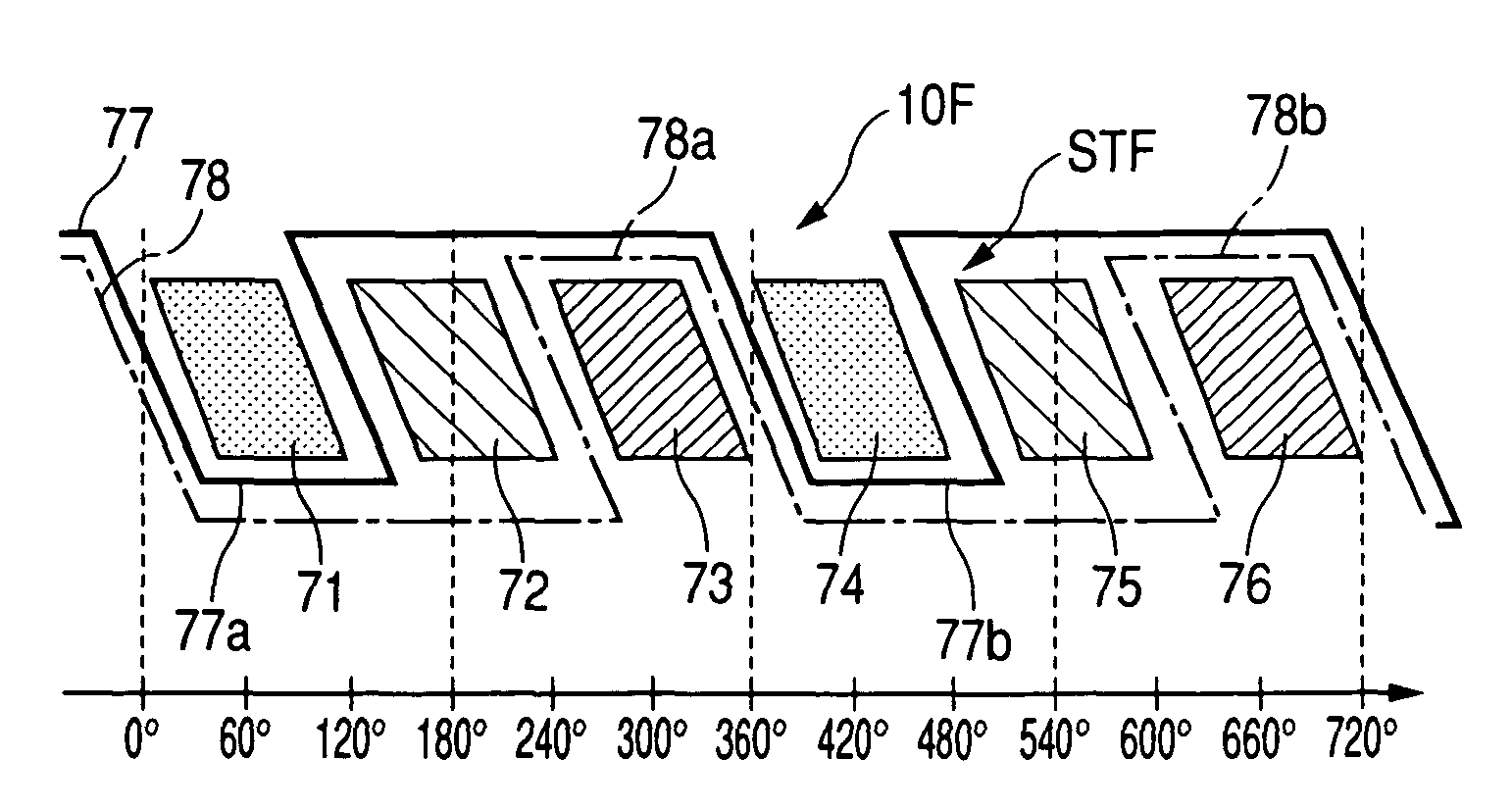
Modified Form of First Embodiment

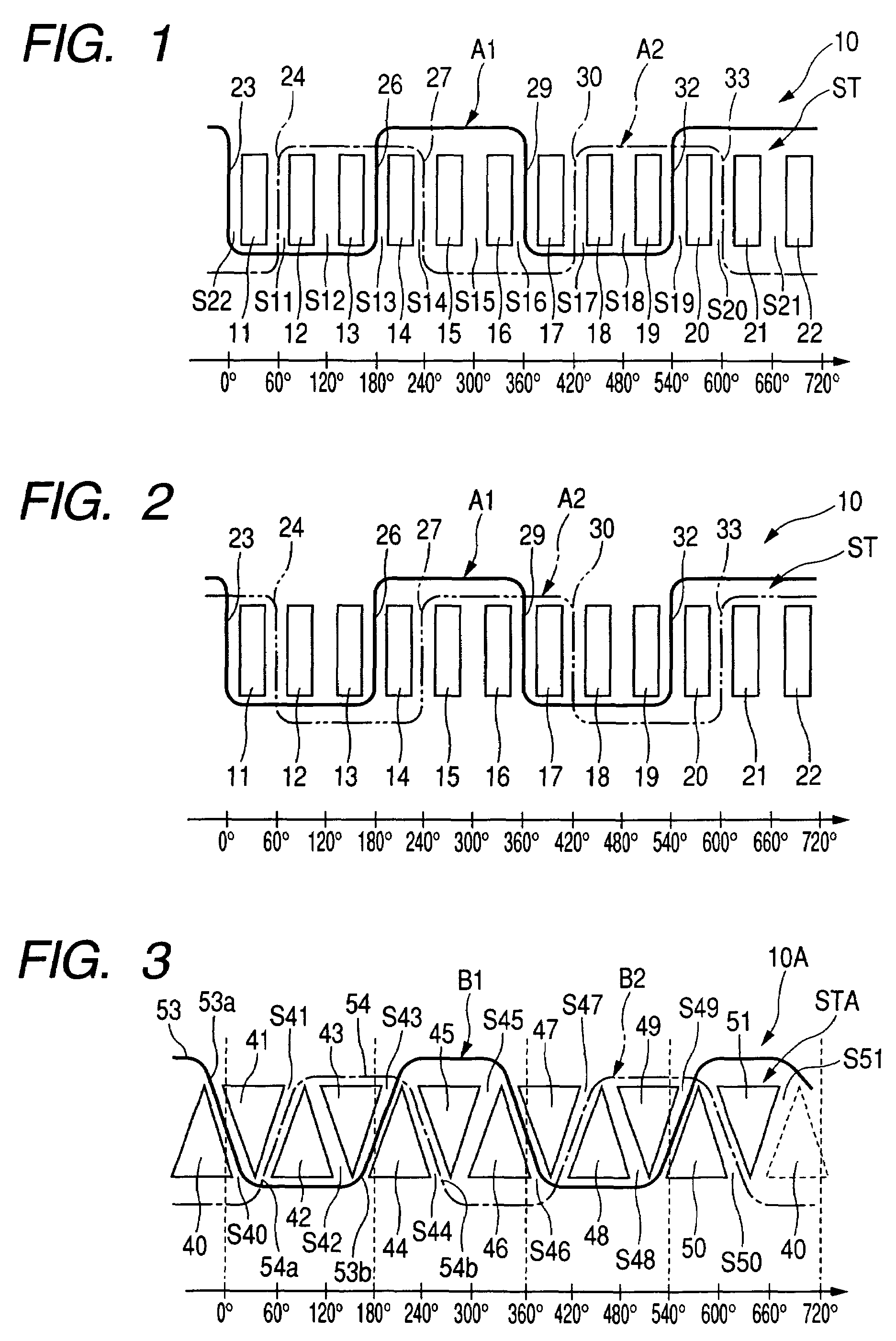
[0076]FIG. 2 shows an exemplary wiring diagram of a stator winding in modified form of the stator winding of the motor 10 shown in FIG. 1.

[0077]In the modified winding pattern shown in FIG. 2, the windings 24, 27, 30, 33 of the W-phase winding A2 are wound in a direction opposite to those of the windings 24, 27, 30, 33 of the W-phase winding A2 shown in FIG. 1. Accordingly, the W-phase winding is connected in opposite wire connection to allow the same current to flow through the winding portions 24, 27, 30, 33. The winding structures, shown in FIGS. 1 and 2, encounter different interfering consequences and, thus, the winding structures may be chosen depending on a manufacturing method.

second embodiment

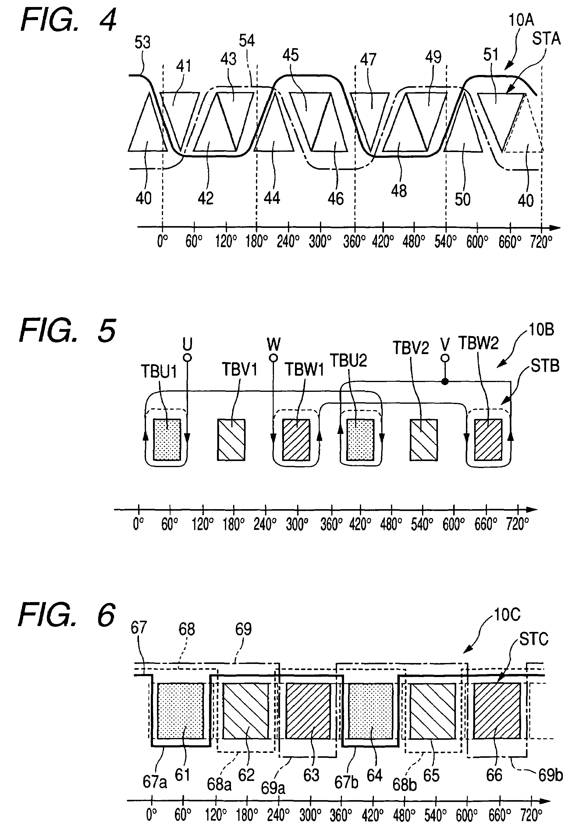
[0078]A brushless motor 10A of a second embodiment according to the present invention is described below with reference to FIG. 3.

[0079]With the brushless motor 10A of the present embodiment, a stator STA has circumferentially spaced stator poles 40 to 51 formed at equidistant positions in triangular configurations, respectively, with the triangular stator poles being alternately disposed on a common circumferential line of the stator STA. The stator STA has slots S40 to S51 each formed between adjacent stator poles.

[0080]With the brushless motor 10A of the present embodiment, the stator STA comprises a U-phase winding 53 and a W-phase winding 54 in the absence of a V-phase winding.

[0081]More particularly, as shown in FIG. 3, the U-phase winding 53 has a winding 53a accommodated in the slot S40, a winding 53b accommodated in the slot S43, a winding 53c accommodated in the slot S46 and a winding 53d accommodated in the slot S49. Likewise, the W-phase winding 54 has a winding 54a acco...

third embodiment

[0087]A brushless motor 10B of a third embodiment according to the present invention is described below with reference to FIG. 5.

[0088]With the brushless motor 10B of the present embodiment, a stator STB comprises concentrated windings such as a U-phase winding composed of U-phase coils TBU1 and TBU2 electrically connected to each other, with a U-phase coil TBU1 having an input connected to a U-phase input terminal, and a W-phase winding composed of W-phase coils TBW1 and TBW2 electrically connected to each other with the W-phase coil TBW1 having an input connected to a W-phase input terminal.

[0089]The U-phase coil TBU2 and the W-phase coil TBW2 have respective output terminals connected to a V-phase terminal. With such a circuit diagram, with the stator STB of the present embodiment, the U-phase coil TBU1 is wound in a clockwise direction. In contrast, with the stator of the related art brushless motor shown in FIG. 29 including the three phase windings, the U-phase coil TBU1 is wo...


PUM


Abstract

A brushless motor and a related control device are disclosed in a structure wherein a stator has U-phase, V-phase and W-phase stator poles, with two of the U-phase V-phase and W-phase stator poles carry thereon respective phase windings, in the absence of a selected phase winding related to a remaining one of the U-phase V-phase and W-phase stator poles. The respective phase windings have end portions connected together at a junction point. A three-phase alternating voltage is applied to the respective phase windings and the junction point to allow the stator to have an electromagnetic action thereby drivably rotating a rotor. The stator poles may be formed in trapezoid shapes to minimize interference between associated component parts for easy assembly in high productivity and efficiency with a reduction in torque ripple.

Description

CROSS REFERENCE TO RELATED APPLICATIONS[0001]This application is based on Japanese Patent Application No. 2006-31446, filed on Feb. 8, 2006, the content of which is hereby incorporated by reference.BACKGROUND OF THE INVENTION[0002]1. Field of the Invention[0003]The present invention relates to motors installed on motor vehicles and trucks and related control devices and, more particularly, to a motor and a related control device for controlling such a motor.[0004]2. Description of the Related Art[0005]Attempts have heretofore been made to provide brushless motors for use in motor vehicle. Such brushless motors include stator poles carrying thereon coils of concentrated windings for respective phases and one of such brushless motor is disclosed in, for instance, Japanese Patent Unexamined Application Publication No. 6-261513 on FIGS. 1 to 3 thereof.[0006]FIG. 27 is a cross sectional view showing a schematic structure of such a related art brushless motor and FIG. 28 is a cross sectio...

Claims


Application Information

Patent Timeline
Patent Type & Authority Patents(United States)
IPC IPC(8): H02K3/00H02K1/16H02K3/28H02K21/14H02P6/06H02P6/08
CPCH02K1/08H02K1/146H02K3/28
Inventor NASHIKI, MASAYUKIMAKITA, SHINJIKAMADA, YOSHINOBU
Owner DENSO CORP
Why Eureka
Try Eureka