Brushless motor and electric power steering apparatus equipped with the brushless motor

a brushless motor and electric steering technology, which is applied in the direction of magnetic circuit rotating parts, magnetic circuit shape/form/construction, transportation and packaging, etc., can solve the problem of uneven air gap between the surface of the magnet secured to the rotor and the rotor-side surface of the stator, and achieves the effect of minimizing influence, enhancing steering wheel feel, and minimizing cogging torqu

Inactive Publication Date: 2005-03-08
HONDA MOTOR CO LTD
View PDF7 Cites 22 Cited by
  • Summary
  • Abstract
  • Description
  • Claims
  • Application Information

AI Technical Summary

Benefits of technology

In the electric power steering apparatus employing any one of the improved or inventive brushless motors capable of minimized cogging torque, it is possible to minimize influences, on the steerable road wheels, of the cogging torque of the motor, for example, in a case where the steering wheel is maneuvered through very small angles around its neutral position, such as during high-speed straight travel of the vehicle. Thus, the present invention can afford a smooth and hence enhanced steering feel of the steering wheel. As a result, the present invention can provide an improved electric power steering apparatus capable of a highly enhanced steering feel.

Problems solved by technology

Because each of the permanent magnets is formed into an asymmetrical sectional shape with respect to an imaginary straight line extending from the center of the rotor at right angles to the surface of the magnet secured to the rotor, the air gap between the surface of the magnet secured to the rotor and the rotor-side surface of the stator is not uniform.

Method used


Image

  • Brushless motor and electric power steering apparatus equipped with the brushless motor
  • Brushless motor and electric power steering apparatus equipped with the brushless motor
  • Brushless motor and electric power steering apparatus equipped with the brushless motor

Examples


second embodiment

FIGS. 12A, 12B and 12C show the inner rotor 75 in the second embodiment, where the permanent magnets 184 are secured to the outer surface of the inner rotor 75. The illustrated example of FIG. 12A assumes that the uppermost position is a 0° angular position which is followed by 90°, 180° and 270° angular positions in the clockwise direction of the figure.

Each of the permanent magnets 184 is divided into halves in the longitudinal or axial direction of the rotation shaft of the rotor 75 (motor shaft 76), to provide two divided magnet members, i.e. first and second divided magnet members 184A and 184B. The first and second divided magnet members 184A and 184B have generally the same length, but the first and second divided magnet members 184A and 184B are positioned along the longitudinal or axial direction of the inner rotor 75 in horizontally opposite orientations.

Specifically, a plurality of the first divided magnet members 184A are collectively placed on one longitudinal half of t...

third embodiment

Next, a description will be given about the brushless motor for use in the electric power steering apparatus, with reference to FIGS. 14 to 17.

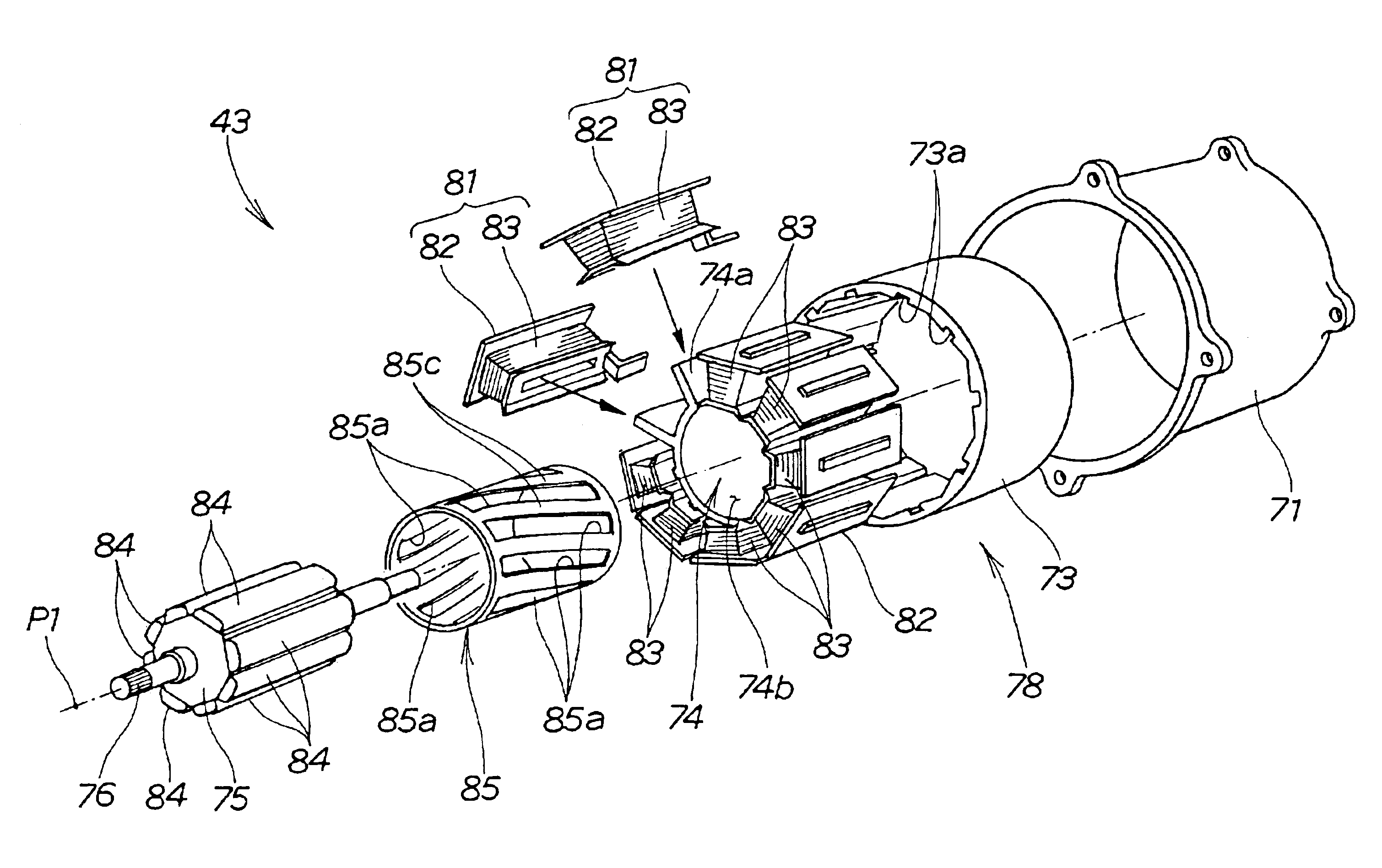
The third embodiment of the brushless motor 243 is different from the second embodiment 143 of FIG. 10 in terms of the construction of the plurality of permanent magnets 284. Except for the permanent magnets 284, the third embodiment 243 is similar in construction to the second embodiment 143. In the third embodiment 243, the elements represented by the same reference numerals as in the second embodiment 143 are constructed in the same manner as the counterparts in the second embodiment 143 and will not be described here to avoid unnecessary duplication. Note that the third embodiment of the brushless motor 243 does not have the magnetic cover 85 of FIG. 3 employed in the first embodiment.

FIG. 15 shows portions of the outer stator 78 and inner rotor 75 of FIG. 14 on a magnified scale.

As seen in FIG. 15, the inner rotor 75 has a sectional shap...

first embodiment

Further, the magnetic cover 85 employed in FIG. 5 maybe formed of any desired magnetic material.

Moreover, each of the permanent magnets 184 and 284 in the second and third embodiment may be divided into any other suitable number of magnet members than just two.


PUM


Abstract

Brushless motor is provided which includes an outer stator and an inner rotor having a plurality of permanent magnets. One or inner surface of the outer stator, opposed to the inner rotor, is covered with a cover formed of a magnetic material and in the shape of a cylinder of a small wall thickness. The magnetic cover has a plurality of slits inclined with respect to the rotational axis of the inner rotor. Magnetic portions formed or left between the slits of the cover are also inclined with respect to the rotational axis of the inner rotor. With such magnetic portions, boundaries between magnetic poles are virtually inclined with respect to the rotational axis of the inner rotor, so that undesired cogging torque of the motor can be minimized.

Description

FIELD OF THE INVENTIONThe present invention relates to an improved brushless motor and an electric power steering apparatus equipped with such an improved brushless motor.BACKGROUND OF THE INVENTIONBrushless motors, which are also called commutator less motors, have electric contacts in place of mechanical contacts such as a commutator and brushes. One example of such brushless motors is disclosed in Japanese Patent Laid-open Publication No. 2001-275325 for “Electric Power Steering Apparatus”. The brushless motor disclosed in the No. 2001-275325 publication is an inner-rotor type brushless D.C. motor, which includes a cylindrical outer stator having a plurality of armature windings provided thereon and an inner rotor rotatably disposed in the outer stator and having a plurality of permanent magnets secured to the circumference thereof.The electric power steering apparatus for a motor vehicle, which is equipped with the brushless motor, is constructed to not only transmit steering to...

Claims


Application Information

Patent Timeline
Patent Type & Authority Patents(United States)
IPC IPC(8): B62D5/04H02K1/27H02K1/14H02K29/03H02K7/116H02K1/18H02K21/14H02K29/00
CPCB62D5/0403H02K1/148H02K29/03H02K1/278H02K2201/06H02K7/1166H02K1/2781
Inventor SHIMIZU, YASUOYONEDA, ATSUHIKOSHIOBARA, HITOSHIKURIBAYASHI, TAKASHI
Owner HONDA MOTOR CO LTD
Why Eureka
Try Eureka