Method and apparatus for reducing image noise

a technology of image noise and reduction method, applied in the field of image processing technology, can solve the problems of blurred captured image and more easily subjected to the influence of noise, and achieve the effect of reducing image noise, simple implementation and saving hardware costs

Active Publication Date: 2014-10-30
FUJITSU LTD
View PDF2 Cites 10 Cited by
  • Summary
  • Abstract
  • Description
  • Claims
  • Application Information

AI Technical Summary

Benefits of technology

[0008]Embodiments of the present invention aim to provide a method and an apparatus for reducing image noise, whereby it is possible to effectively reduce image noise, to be simply implemented, and to save the cost of hardware.
[0009]According to the first aspect of the embodiments of the present invention, there is provided a method for reducing image noise, which method includes:
[0021]Effects of the embodiments according to the present invention are as follows: by using luminance information to process chrominance or color channel images, it is possible to effectively reduce image noise, to be simply implemented, and to save the cost of hardware.

Problems solved by technology

An image captured when ISO is set relatively low has less noise and vivid colors, but the captured image tends to blur due to slow shutter speed.
An image captured when ISO is set relatively high and brightness is relatively low has higher image sensor gain, and is seldom affected by blurring, but is more easily subject to the influence of noise as compared with the case in which ISO is set relatively low.

Method used


Image

  • Method and apparatus for reducing image noise
  • Method and apparatus for reducing image noise
  • Method and apparatus for reducing image noise

Examples


embodiment 1

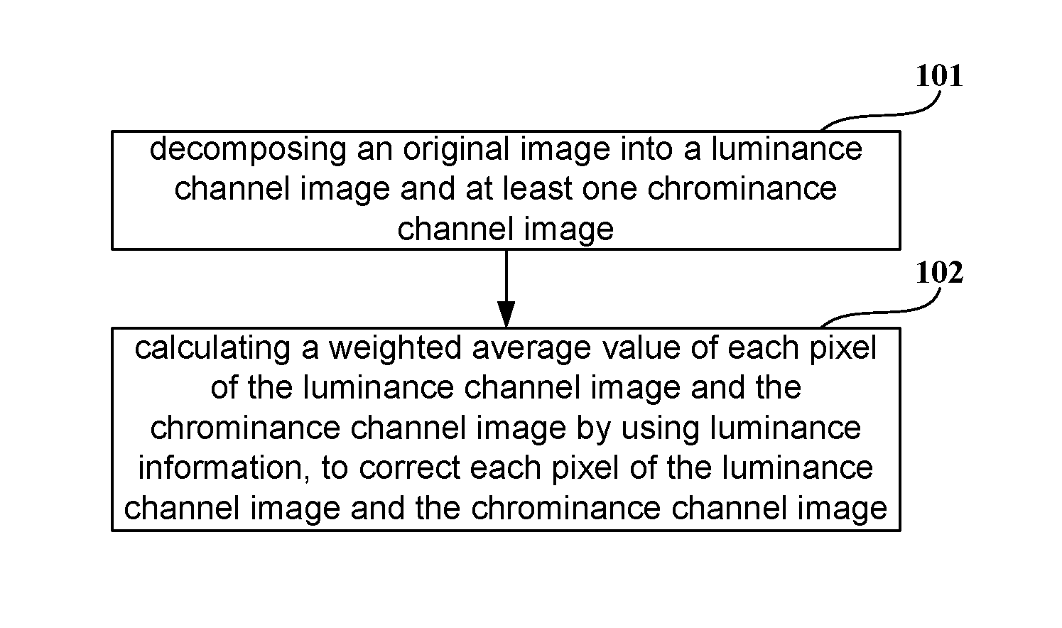
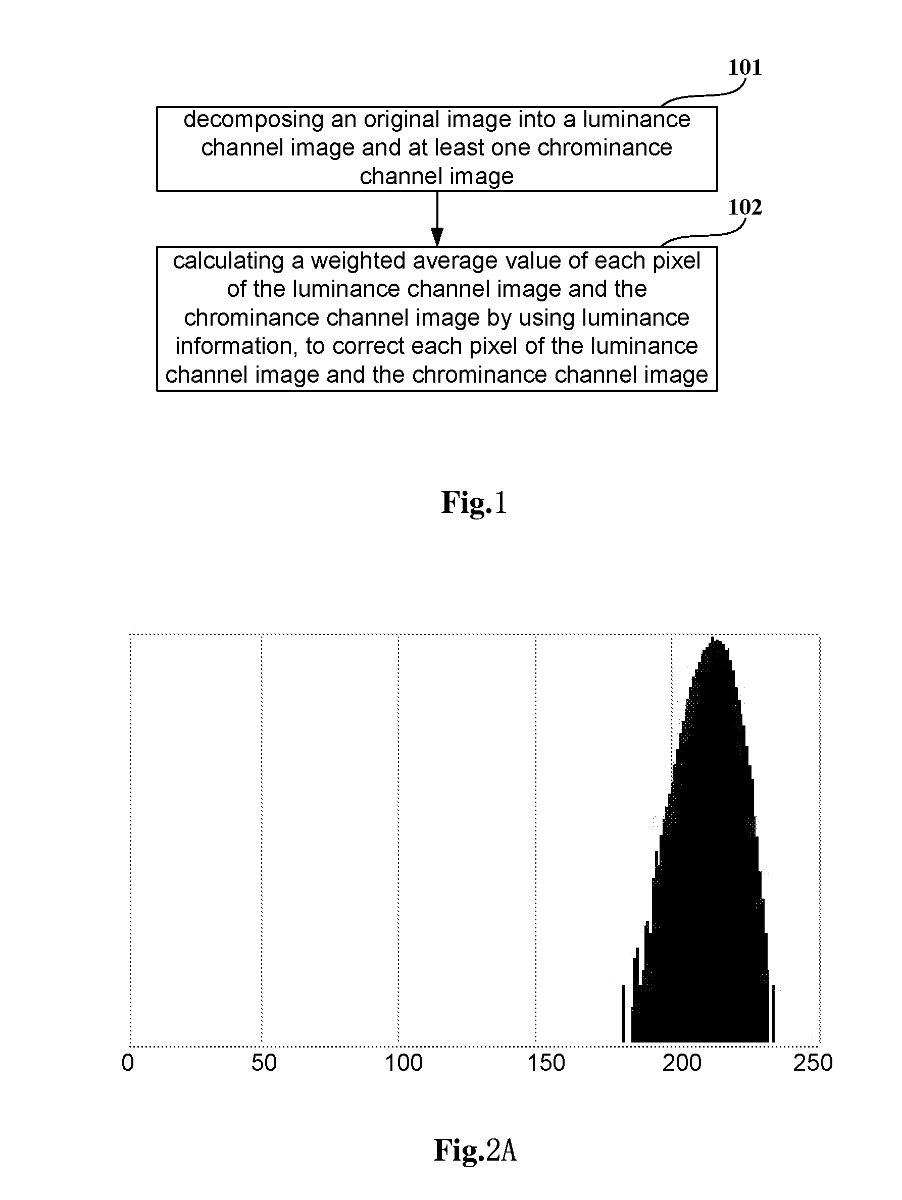
[0033]FIG. 1 is a flowchart illustrating a method for reducing image noise according to Embodiment 1 of the present invention which may be performed by a processor. As shown in FIG. 1, the method includes the following steps.

[0034]Step 101—decomposing an original image into a luminance channel image and at least one chrominance channel image.

[0035]Any currently available technique may be employed in this embodiment to decompose color space, and this will not be redundantly described in the context.

[0036]Wherein, the number of chrominance channels may be equal to or greater than 2, and this can be determined according to practical circumstances—for instance, three channels are divided according to color space, e.g. (Y, Cb, Cr), Cb and Cr correspond to chrominance channels, Y corresponds to a luminance channel; alternatively, (Y, U, V), U and V correspond to chrominance channels, and Y corresponds to a luminance channel.

[0037]Step 102—calculating a weighted average value of each pixel...

embodiment 2

[0047]Embodiment 2 of the present invention further provides a method for reducing image noise which may be performed by a processor. This method is based on Embodiment 1 and differs therefrom in obtaining a luminance weight value by employing a mode according to this embodiment.

[0048]The luminance weight is obtained by using the following expression:

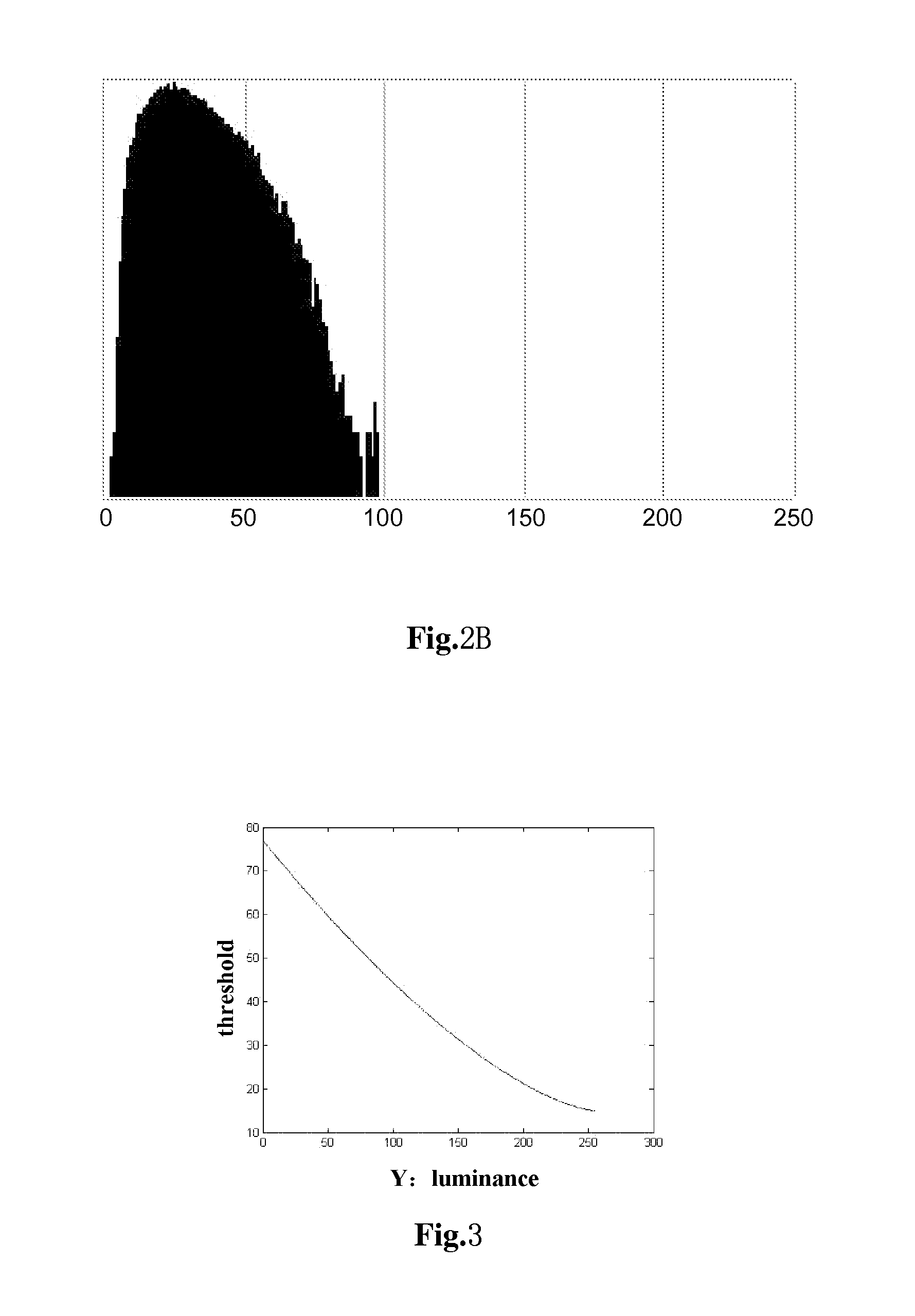
WY(x,y)={(1-DYthe_Y)aDYthe_Y0DY≥the_Y;(3-2)

[0049]where the—Y represents a first threshold, and a represents a parameter relevant to noise characteristics in a flat region containing the current pixel.

[0050]In this embodiment, the flat region containing the current pixel is a non-boundary region of an object, and the surrounding pixels are relevant to the current pixel, while pixels on the boundary are far less relevant to objects at two sides surrounding the boundary.

[0051]In this embodiment, the a may either be empirically preset or determined according to practical circumstances—for instance, the a may be evaluated as 2, 1.5, 1.2 or 1...

embodiment 3

[0057]Embodiment 3 of the present invention further provides a method for reducing image noise. This method is based on Embodiment 1 and differs therefrom in obtaining a distance weight value by employing a mode according to this embodiment.

[0058]The distance weight is obtained by using the following expression:

Wd(x,y)=1Rb+1(4-2)

[0059]where R represents a distance of the pixel to be measured to the current pixel in the predetermined region, and b represents a parameter relevant to noise characteristics.

[0060]Similar to a, the value of b may either be preset or predetermined according to practical circumstances.

[0061]In addition, the b may also be auto-adaptively obtained according to a range of color noise, wherein a value of b is smaller when the range of the color noise is great than a value of b when the range of the color noise is small. For instance, depending on noise characteristics, when the range of the color noise is very large, noise should be averagely reduced by using i...


PUM


Abstract

Embodiments of the present invention provide a method and an apparatus for reducing image noise. The method includes decomposing an original image into a luminance channel image and at least one chrominance channel image, and calculating a weighted average value of each pixel of the luminance channel image and the chrominance channel image by using luminance information, to correct each pixel of the luminance channel image and the chrominance channel image. By virtue of the embodiments of the present invention, it is possible to effectively avoid color dispersion at edges of images, to achieve easy implementation, and to effect low cost.

Description

CROSS-REFERENCE TO RELATED APPLICATIONS[0001]This application claims the benefit of Chinese Application No. 201310150233.5, filed Apr. 26, 2013, the disclosure of which is incorporated herein by reference.BACKGROUND[0002]1. Field[0003]The present invention relates to image processing technology, and more particularly to a method and an apparatus for reducing image noise.[0004]2. Description of the Related Art[0005]In digital cameras, ISO is a parameter that indicates image sensor gain. An image captured when ISO is set relatively low has less noise and vivid colors, but the captured image tends to blur due to slow shutter speed. An image captured when ISO is set relatively high and brightness is relatively low has higher image sensor gain, and is seldom affected by blurring, but is more easily subject to the influence of noise as compared with the case in which ISO is set relatively low.[0006]As should be noted, the foregoing introduction to the background of the art is merely meant...

Claims


Application Information

Patent Timeline
Patent Type & Authority Applications(United States)
IPC IPC(8): G06T5/00
CPCG06T5/002G06T5/20G06T5/40G06T2207/10004G06T2207/10024G06T2207/20012H04N1/409
Inventor FU, XUANYE, JIANGLI
Owner FUJITSU LTD
Why Eureka
Try Eureka