
Guiding device which is intended to be interposed between a device for fixing components of an assembly, and a device for protecting the fixing device

a technology for fixing components and fixing devices, which is applied in the direction of threaded fasteners, screwing, manufacturing tools, etc., can solve the problems of hot gases released at the side of the crimping ring, ineffective guiding of the protection device, and deformation of the ring geometry, so as to improve the ability to repeat the operation

Active Publication Date: 2014-10-30
AIRBUS OPERATIONS (SAS) +1
View PDF9 Cites 11 Cited by
  • Summary
  • Abstract
  • Description
  • Claims
  • Application Information

AI Technical Summary

Benefits of technology

The invention is better because it separates from existing methods that depend on a crimping ring to guide the protection device. It introduces an additional guiding device that improves the positioning of the protection device around the fixing device. This is because the guiding is no longer dependent on the ring's geometry, which can change over time. In summary, the invention results in better and more reliable guiding for positioning the protection device.

Problems solved by technology

The sparking leads to heating of the air in the zone of the bore of the components, possibly resulting in a release of hot gases at the side of the crimping ring.
Satisfactory fitting of the protection device on the assembly requires above all correct positioning thereof relative to the fixing device which it covers.
Nevertheless, after the crimping operation, the ring has a deformed geometry resulting from the creep of material brought about by this same crimping operation.
The deformed ring, although it provides satisfactory clamping, can be found to be ineffective in ensuring the guiding required for the protection device.
It should further be noted that this risk is increased when an inclination exists between the axis of this crimping ring and the normal relative to the surface of the non-metal component against which this ring is in abutment.

Method used


Image

  • Guiding device which is intended to be interposed between a device for fixing components of an assembly, and a device for protecting the fixing device
  • Guiding device which is intended to be interposed between a device for fixing components of an assembly, and a device for protecting the fixing device
  • Guiding device which is intended to be interposed between a device for fixing components of an assembly, and a device for protecting the fixing device

Examples


Embodiment Construction

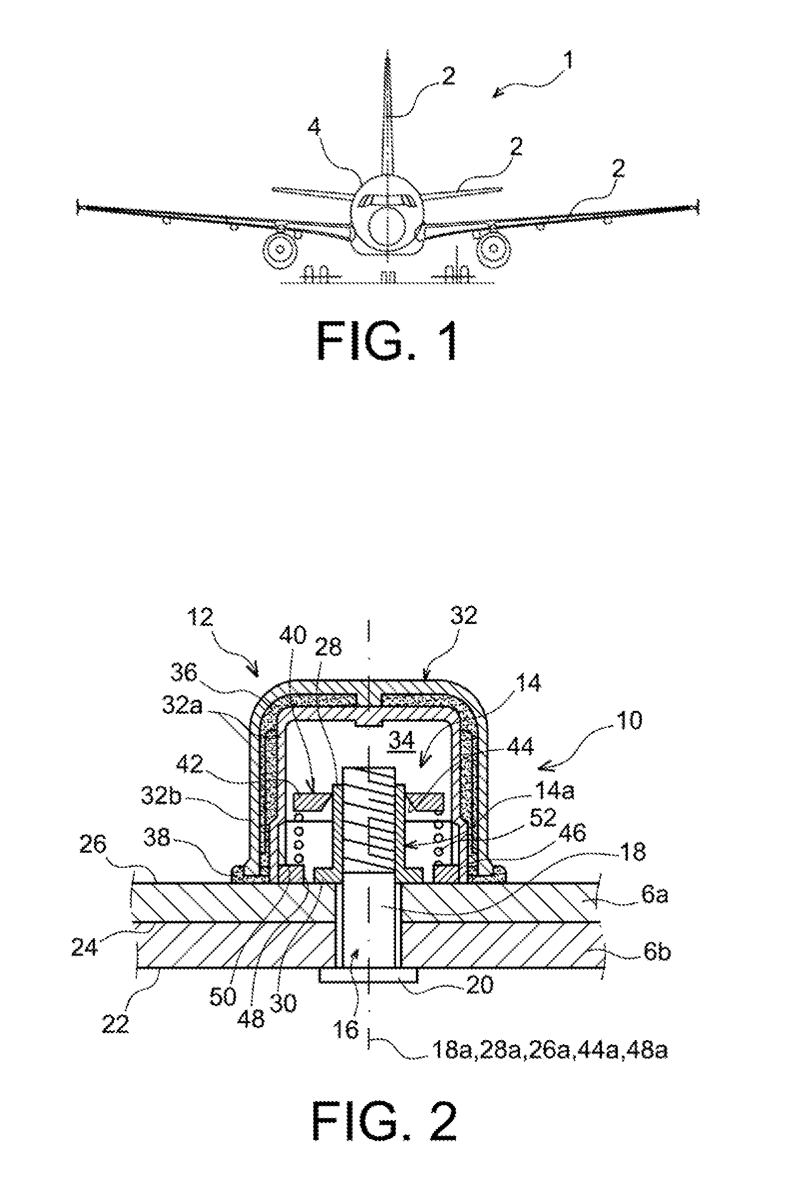
[0049]FIG. 1 illustrates an aircraft 1 which is intended to incorporate one or more assemblies according to the invention, for example, in the region of the wings 2 and / or in the region of the fuselage 4 thereof.

[0050]The invention involves the assembly of at least two non-metal components with each other, for example, panels or the like. The stacked components are preferably of composite material, produced from a mixture of fibers and a resin. There are preferably used carbon fibers having an intermediate modulus “IM” and an epoxy resin, optionally charged with nodules of thermoplastic resin. This composition substantially weakens the electrical conductivity of the components. There is consequently a need to protect the assembly against specific phenomena linked to the lightning strike, these phenomena in particular being those described above.

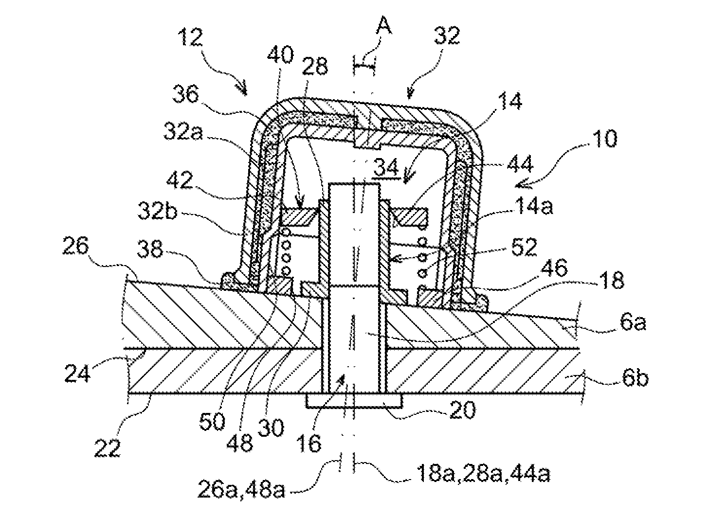
[0051]In the first embodiment shown in FIG. 2, the assembly 10 comprises two stacked components 6a, 6b of composite material. They are fixed...


PUM

PropertyMeasurementUnit
angleaaaaaaaaaa
resilientaaaaaaaaaa
frictionaaaaaaaaaa

Abstract

An assembly comprising at least two non-metal components which are fixed to each other using at least one fixing system. The fixing system includes a fixing device with a fixing element which is provided with a head and a rod, and a crimping ring which is in contact with one of the components. A protection device is a part of the fixing system which delimits a cavity for confining gas around a portion of the device comprising the crimping ring. In order to improve the repeatability of the operation for positioning the protection device, a guiding device is provided which includes an assembly element on the portion of the fixing device, and an element for guiding the protection device.

Description

CROSS-REFERENCES TO RELATED APPLICATIONS[0001]This application claims the benefit of the French patent application No. 201353976 filed on Apr. 30, 2013, the entire disclosures of which are incorporated herein by way of reference.BACKGROUND OF THE INVENTION[0002]The present invention relates to the field of component assemblies, comprising at least one fixing device which is provided with a crimping ring. The invention more specifically relates to positioning a device for protecting the fixing device against the risks linked with lightning strikes.[0003]The invention is very preferably used for assemblies for aircraft.[0004]The fixing of non-metal components can be carried out with devices of the type comprising, on the one hand, a fixing element which is provided with a rod having a head and, on the other hand, a crimping ring. Using such crimped fixing devices, the components are clamped between the head and the crimping ring in order to carry out the plating thereof.[0005]In parti...

Claims


Application Information

Patent Timeline
Patent Type & Authority Applications(United States)
IPC IPC(8): F16B33/00B64D47/00
CPCB64D47/00F16B33/004B64D45/02F16B5/025F16B19/05F16B37/14F16B39/025F16B33/02Y10T29/49925
Inventor CHIROL, CLEMENTCRESSWELL, PHILIPDAPOT, FLORIAN
Owner AIRBUS OPERATIONS (SAS)
Learn More