Electrical connector and manufacturing method thereof

a technology of electrical connectors and manufacturing methods, applied in the field of electrical connectors, can solve the problems of small contact load between both, damage to electrical reliability, and insufficient displacement, and achieve the effects of reducing slide wear, stable conduction, and improving electrical reliability

Active Publication Date: 2014-10-30
YAZAKI CORP +1
View PDF4 Cites 3 Cited by
  • Summary
  • Abstract
  • Description
  • Claims
  • Application Information

AI Technical Summary

Benefits of technology

[0018]According to the electrical connector of the present invention, in an electrically connected state in which the male tab of the male connector is inserted into the housing part of the female connector, the protrusion is accepted by the recessed part, and thereby, a move of the male tab sandwiched between the contact piece and the beat piece is prevented. Accordingly, it is possible to reduce the slide wear as much as possible. Besides, the slide is prevented by the combination of the protrusion and the recessed part at a part different from a part enabling an electrical contact to separate two functions of an electric contact part and a fixed part. As a result, both the surely suppression of the slide distance by the fixed part, and the stable conduction by the electric contact part are enabled, and electrical reliability improves.

Problems solved by technology

However, in a small-sized terminal, sheet thicknesses of materials used for the male tab at the male connector side and the contact piece at the female connector side become thin, and therefore, a contact load becomes small, further, it is impossible to keep an enough displacement amount, and therefore, the contact load between both becomes small.
In case of the Sn plating which is widely used to guarantee electrical reliability at a terminal contact point, it is known that the electrical reliability is damaged by minute slide wear caused by minute slide if the contact load is small.
Besides, a measure to enable a standstill contact point by devising a terminal shape can be cited, but the contact point is easy to move when the contact load is small, and it is difficult to suppress the minute slide wear because the slide wear is generated by the slide in a minute distance.
In particular, in the technologies of Patent Documents 1, 3, a contact point between the female terminal and the male terminal to be an electric contact is made to be a combination of recession and projection to suppress the slide distance, and therefore, the contact is easy to be unstable.
Besides, in the technologies of Patent Documents 2, 3 the contact point to suppress the slide distance and the electric contact are separately provided, but a complicated spring structure is required to add a high contact load to suppress the slide distance.
. . ”, and it is conceivable that an effect to suppress the slide distance is not sufficient.

Method used


Image

  • Electrical connector and manufacturing method thereof
  • Electrical connector and manufacturing method thereof
  • Electrical connector and manufacturing method thereof

Examples


Embodiment Construction

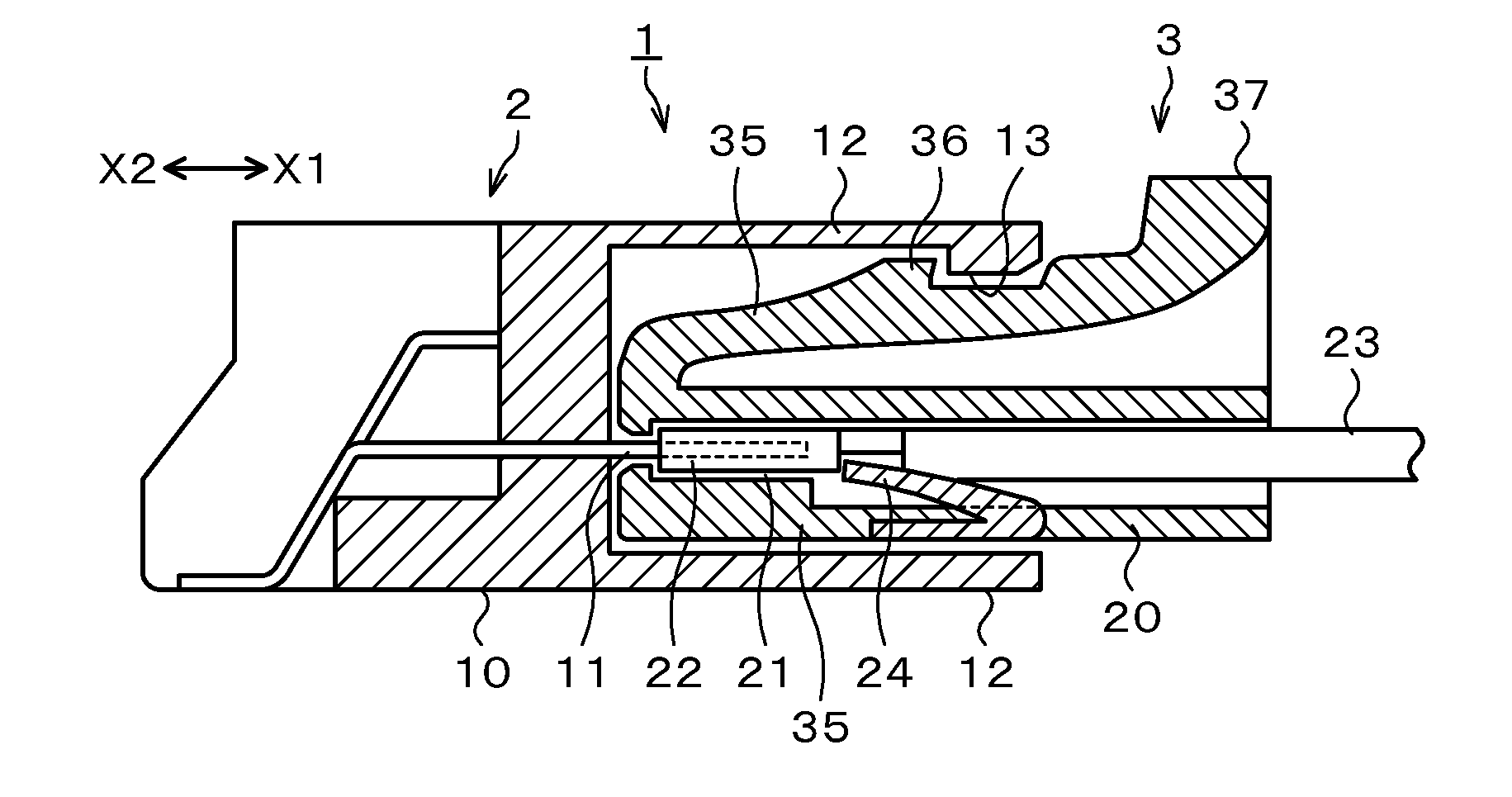
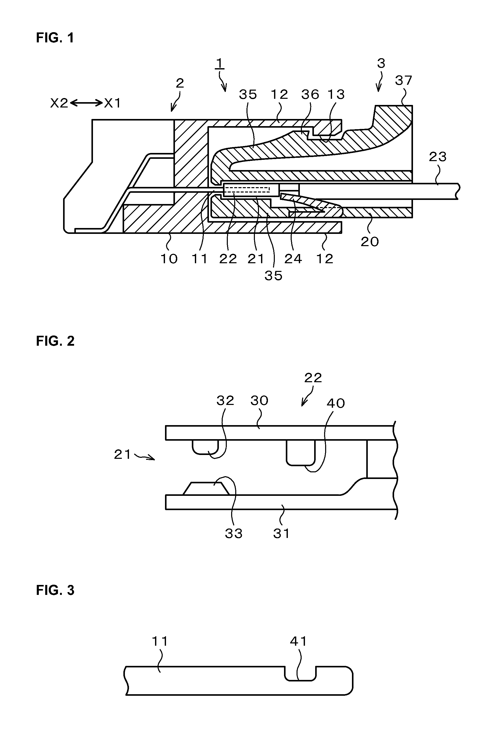
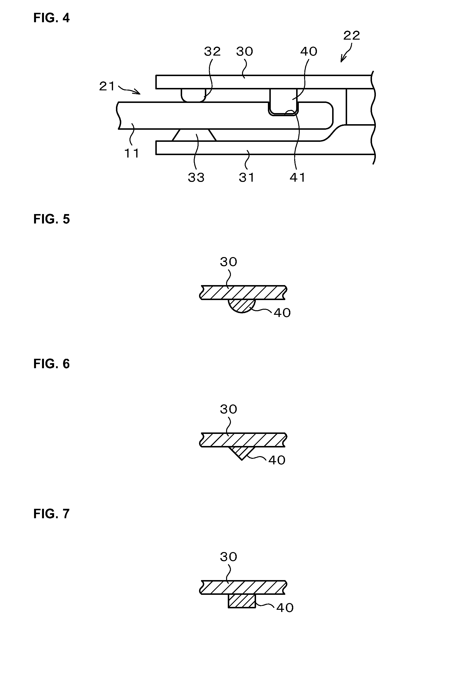
[0031]Hereinafter, an example of an embodiment of the present invention is described with reference to the drawings. Note that in the description and the drawings, the same reference numerals and symbols are used to designate components having substantially the same functional configuration, and the redundant description thereof will not be given. As illustrated in FIG. 1, an electrical connector 1 according to the present embodiment includes a male connector 2 and a female connector 3 which are connectable in a freely engageable and detachable manner with each other.

[0032]The male connector 2 illustrated at a left side in FIG. 1 has a constitution in which a male tab 11 made up of a conductive material as a male terminal protrudes at a tip surface of a male side resin molding part 10. A cylindrical male side cover 12 disposed to surround a periphery of the male tab 11 is provided at the male side resin molding part 10. A male side engaging lock 13 is provided toward inside at an in...


PUM

PropertyMeasurementUnit
thicknessesaaaaaaaaaa
thicknessaaaaaaaaaa

Abstract

An electrical connector connecting a male connector and a female connector in a freely engageable and detachable manner includes, a male tab is provided at the male connector; a housing part where the male tab is inserted is provided at the female connector; a contact piece and a beat piece to hold and press the male tab to enable electrical connection are provided at the housing part; and a protrusion is provided at least at one of the contact piece and the beat piece, and a recessed part capable of accepting the protrusion is provided at the male tab, wherein the contact piece, the beat piece, and the protrusion are constituted to be one component.

Description

TECHNICAL FIELD[0001]The present invention relates to an electrical connector to easily and surely perform an electrical connection and disconnection. This application is based upon and claims the benefit of priority of the prior Japanese Patent Application No. 2012-9929, filed on Jan. 20, 2012, and Japanese Patent Application No. 2013-6912, filed on Jan. 18, 2013, the entire contents of which are incorporated herein by reference.BACKGROUND ART[0002]For example, an electrical connector connecting a female connector and a male connector in a freely engageable and detachable manner is used for an electrical connection of a vehicle, an electronic equipment, and so on. When the electrical connector is connected and disconnected, a male tab at the male connector side inserted into the female connector and a contact piece which is electrically connected to the male tab at the female connector side slide with each other, and wear debris are generated.[0003]In general, Sn plating is perform...

Claims


Application Information

Patent Timeline
Patent Type & Authority Applications(United States)
IPC IPC(8): H01R4/48H01R43/16
CPCH01R43/16H01R4/48H01R13/04H01R13/111H01R13/20Y10T29/49204
Inventor NAKAMURA, MASATOSHIONODERA, AKIFUMISUGAWARA, AKIRANARIEDA, HIROTOMURATA, TATSUNORI
Owner YAZAKI CORP
Why Eureka
Try Eureka