Cam device

A technology of cam device and cam groove, applied in the direction of cam, transmission device, cam follower, etc., to achieve the effects of improved durability, reduced sliding wear, and reduced wear

Inactive Publication Date: 2005-03-23
ZUIKO CORP
View PDF0 Cites 1 Cited by
  • Summary
  • Abstract
  • Description
  • Claims
  • Application Information

AI Technical Summary

Problems solved by technology

[0002] like Image 6 As shown, in this type of detent cam, the first and second side walls 101, 102 of the cam groove 100 tend to make the cam follower 200 rotate in opposite directions, which is generally not suitable for high-speed motion as is well known.

Method used


Image

  • Cam device
  • Cam device
  • Cam device

Examples


Embodiment Construction

[0023] The present invention will be more clearly understood by describing the following preferred embodiments with reference to the accompanying drawings. However, the embodiments and drawings are only for illustration and description. The scope of the invention is defined by the claims. In the drawings, the same reference numerals in different drawings indicate the same or corresponding parts.

[0024] Hereinafter, embodiments of the present invention will be described with reference to the drawings.

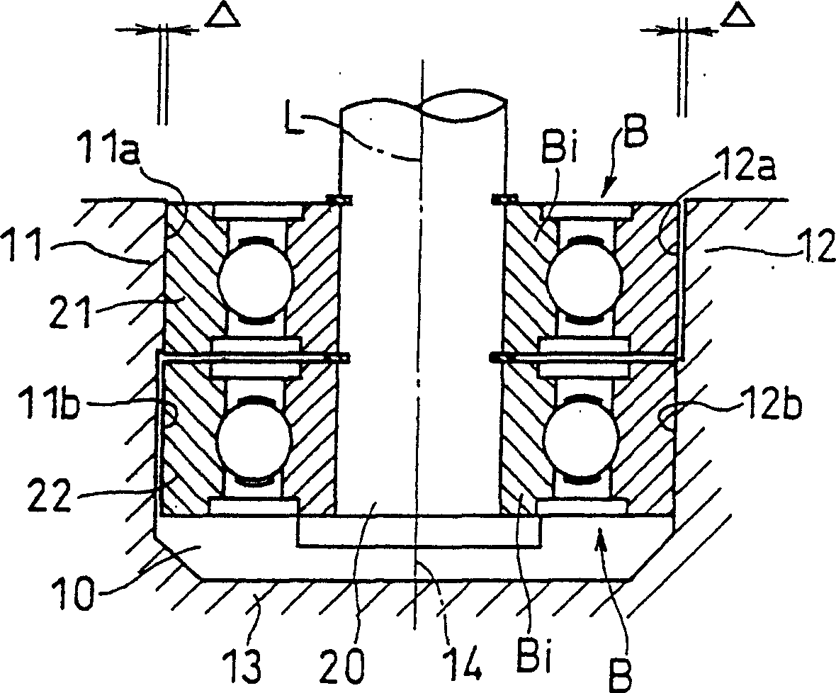
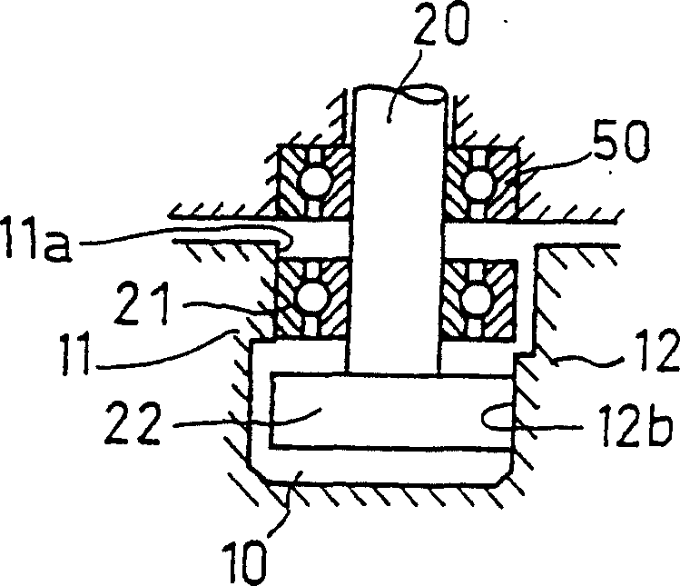
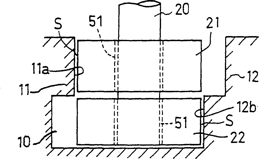
[0025] In the cam device of this embodiment, if figure 2 As shown in the cylindrical cam 1 shown in FIG. 1 , along an annular cam groove 10 formed on a curved surface, the outer peripheral surfaces of the first and second cam followers 21 and 22 perform predetermined movements while rotating.

[0026] On the outer periphery of the front end portion of the shaft 20 shown in FIG. 1( a), first and second cam followers 21 and 22 are respectively freely rotatable, and are arran...


PUM


Abstract

The inveniton relates to a cam device. This cam device has freely rotatable cam-followers for making prescribed motion along a groove 10 formed of first and second side walls 11 and 12. The individually freely rotatable first and second cam-followers 21 and 22 are arranged in a pair, the axes L of the pair of cam-followers 21 and 22 are set so as to mutually become the same direction, the motion of the first cam-follower 21 is regulated by at least a part of the first side wall 11, and the motion of the second cam-follower 22 is regulated by at least a part of the second side wall 12. The cam device has excellent durability.

Description

technical field [0001] The present invention relates to a cam arrangement (definite cam) in which a freely rotatable cam follower (rotor) moves along a slot. Background technique [0002] Such as Figure 6 As shown, in this type of detent cam, the first and second side walls 101, 102 of the cam groove 100 tend to rotate the cam follower 200 in opposite directions, which is generally not suitable for high-speed motion as is well known. That is, when the cam follower 200 moves relatively in the arrow X direction along the cam groove 100 , it rotates and advances clockwise while rolling in contact with the first side wall 101 at the first position P1 . In the second position P2, it rotates and advances in the counterclockwise direction while making rolling contact with the second side wall 102 . [0003] Therefore, during the movement of the cam follower 200 from the first position P1 to the second position P2, the rotation direction is reversed, so that the cam follower 200 i...

Claims


Application Information

Patent Timeline
Patent Type & Authority Patents(China)
IPC IPC(8): F16H53/08F16H25/12F16H53/00F16H53/06
CPCY10T74/2107F16H53/06F16H25/12Y10T74/18312
Inventor 中门正毅
Owner ZUIKO CORP
Why Eureka
Try Eureka