Hard-rolling roller

a roller and roller technology, applied in metal rolling, grooves, mechanical equipment, etc., can solve the problems of improper installation of the roller, -the roller and the crankshaft are incorrectly machined, and the roller is not intended to prevent improper installation

Active Publication Date: 2014-11-06
HEGENSCHEIDT MFD
View PDF4 Cites 11 Cited by
  • Summary
  • Abstract
  • Description
  • Claims
  • Application Information

AI Technical Summary

Benefits of technology

[0005]According to the invention, this task is solved by the fact that a cyli

Problems solved by technology

The consequences are premature wear of the cage and the hard-rolling rollers and an incorrectly machine

Method used


Image

  • Hard-rolling roller
  • Hard-rolling roller
  • Hard-rolling roller

Examples


Embodiment Construction

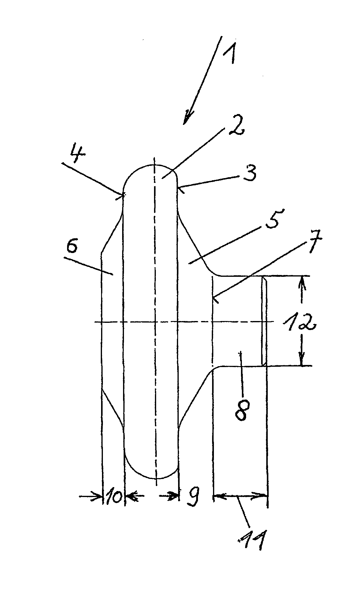
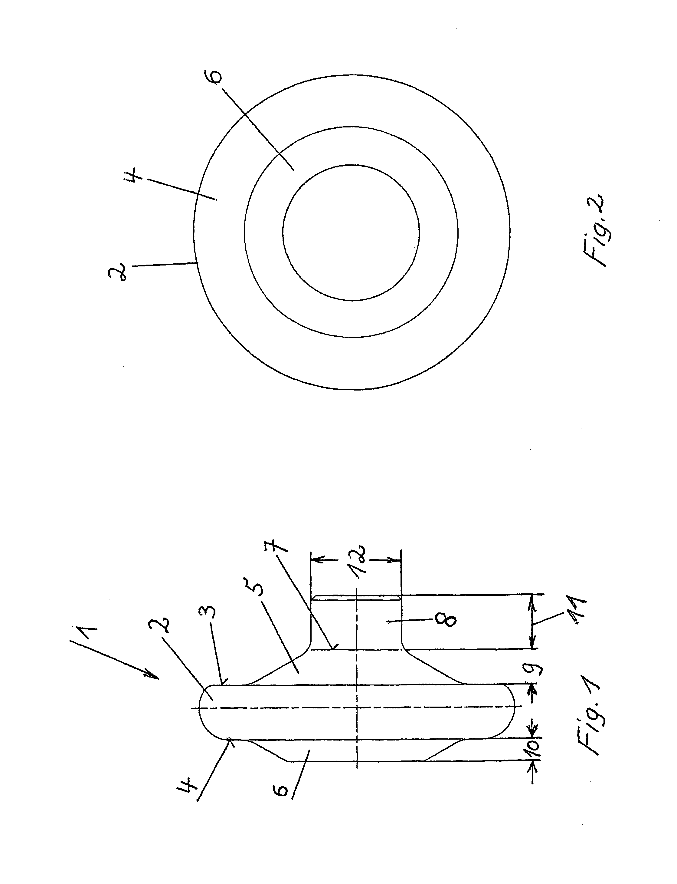
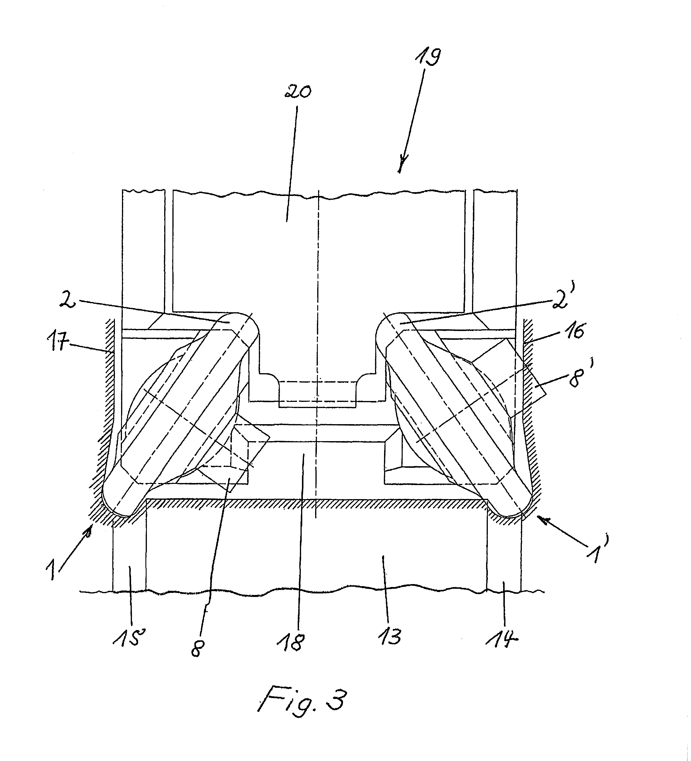
[0011]Hard-rolling roller 1 has a torus-shaped base body 2 for deep rolling of radiuses or recesses 14, 15 which limit the bearing trunnions 13 at the crankshafts (not shown) on both sides. The truncated cone-shaped central bodies 5 and 6 rise on both sides 3 and 4 of the base body 2. A cylindrical body 8 rises on the upper end surface 7 of the one central body 5. For example, the two central bodies 5 and 6 have differing heights 9 and 10. These height differences, however, are not absolutely necessary, so that the two heights 9 and 10 can also be the same. It is so that the height of central body 6 which does not support cylindrical body 8 can also be zero.

[0012]The cylindrical body 8, in turn, has a height 11 which is at least as high as the height 9 of the central body 5. However, it is preferable if the height 11 of the cylindrical body 8 is larger than the height 9 of the central body 5 which supports the cylindrical body 8. The diameter 12 of the cylindrical body 8 corresponds...


PUM

PropertyMeasurementUnit
Diameteraaaaaaaaaa
Heightaaaaaaaaaa

Abstract

The invention relates to a hard-rolling roller for a deep rolling tool having a torus-shaped base body for deep rolling of radiuses or recesses which limit the bearing trunnion on crankshafts on both sides, and two at least approximately truncated cone-shaped central bodies, rising on both sides of the body. A cylindrical body rises on the upper end surface of one of the two central bodies.

Description

CROSS-REFERENCE TO RELATED APPLICATIONS[0001]This application is a 371 U.S. National Stage of International Application No. PCT / DE2012 / 000750, filed Jul. 20, 2012, which claims priority to German Patent Application No. 20 2011 103 888.6, filed Jul. 28, 2011. The entire disclosures of the above applications are incorporated herein by reference.FIELD[0002]The invention relates to a hard-rolling roller for a deep rolling tool with a torus-shaped base body for deep rolling of radiuses or recesses which limit the bearing trunnions on crankshafts on both sides and two cone-shaped central bodies which are at least approximately truncated that rise on both sides of the base body.BACKGROUND AND SUMMARY[0003]Hard-rolling rollers generally have the shape of a low truncated cone. The base area of these truncated cones is very rounded at the edges, sometimes with different radiuses, which results in a nearly torus-shaped body. Hard-rolling rollers of the designated type are known, for example, f...

Claims


Application Information

Patent Timeline
IPC IPC(8): B24B39/04
CPCB24B39/04B21H7/185B23P9/02B24B39/003B24B39/045Y10T29/17
Inventor STEFFENS, HANS-TONIZIMMERMANN, HANS
Owner HEGENSCHEIDT MFD
Why Eureka
Try Eureka