Vehicle battery mounting structure

a technology for mounting structures and battery packs, applied in the direction of batteries/cells, cell components, propulsion by batteries/cells, etc., can solve problems such as poor workability, achieve the effects of improving workability, reducing the amount of slide of the vehicle seat, and increasing the capacity of rainwater

Active Publication Date: 2014-11-06
TOYOTA JIDOSHA KK
View PDF22 Cites 22 Cited by
  • Summary
  • Abstract
  • Description
  • Claims
  • Application Information

AI Technical Summary

Benefits of technology

[0025]With the vehicle battery mounting structure according to the above aspect, the distal end portion of the seal member in the direction in which the seal member extends is curved so as to be oriented toward a side opposite to the service hole. By so doing, in comparison with the configuration that the distal end portion of the seal member in the direction in which the seal member extends is not curved, it is possible to increase the capacity of rain water, or the like, stored between the base portion and the seal member while suppressing entry of rain water, or the like, toward the service hole side through the gap between the vehicle floor and the top wall portion of the battery case. Thus, a failure, or the like, of the operating portion is further suppressed.
[0026]As described above, with the vehicle battery mounting structure according to the aspect of the invention, it is possible to reduce the amount of slide of the vehicle seat while improving workability of work for removing the service hole cover.

Problems solved by technology

However, in the electric vehicle described in JP 2009-083601 A, the boot mounting hole and the cap member are located below the front seat as described above, so, when a worker operates the service plug, it is required to, for example remove the cap member in a narrow space between the floor panel and the front seat, resulting in poor workability.

Method used


Image

  • Vehicle battery mounting structure
  • Vehicle battery mounting structure
  • Vehicle battery mounting structure

Examples


Embodiment Construction

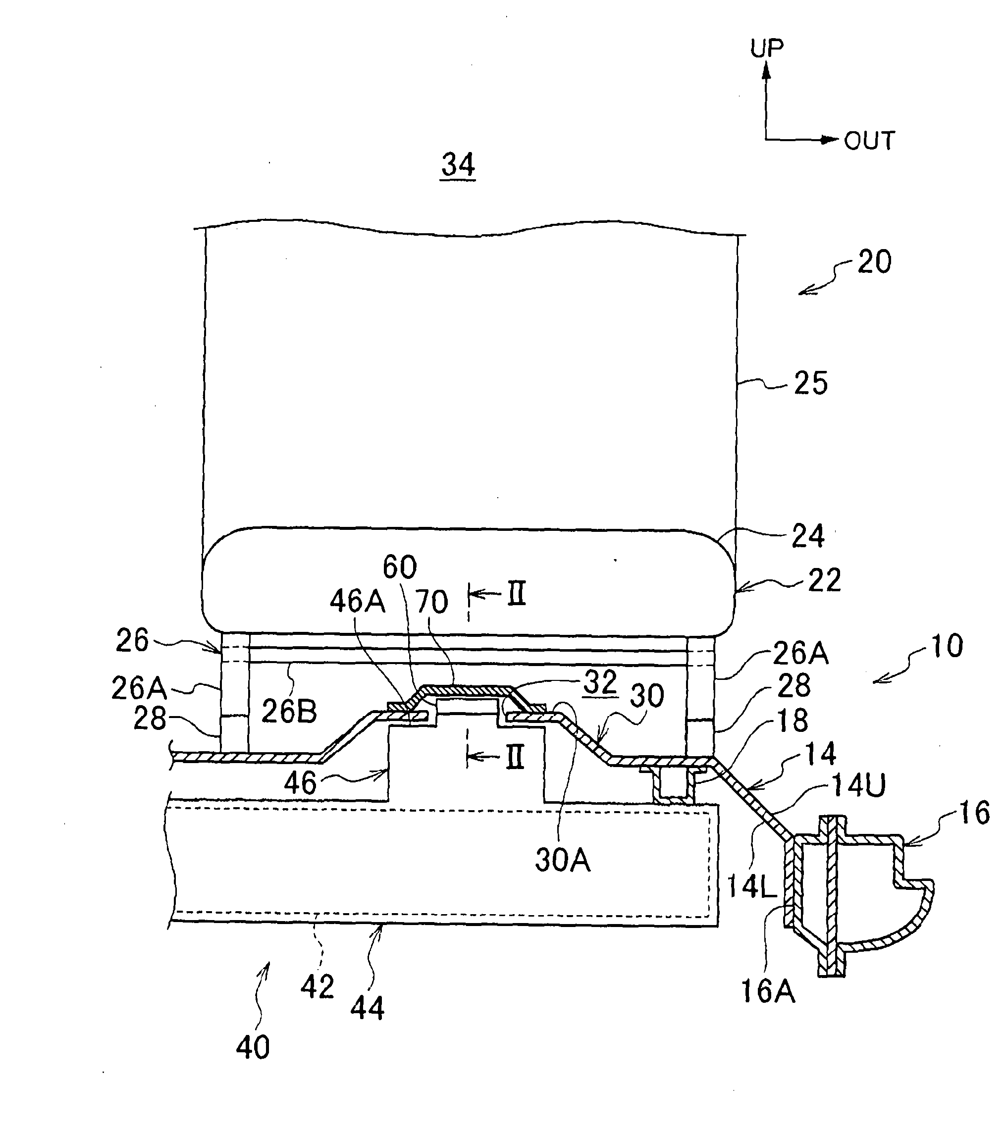
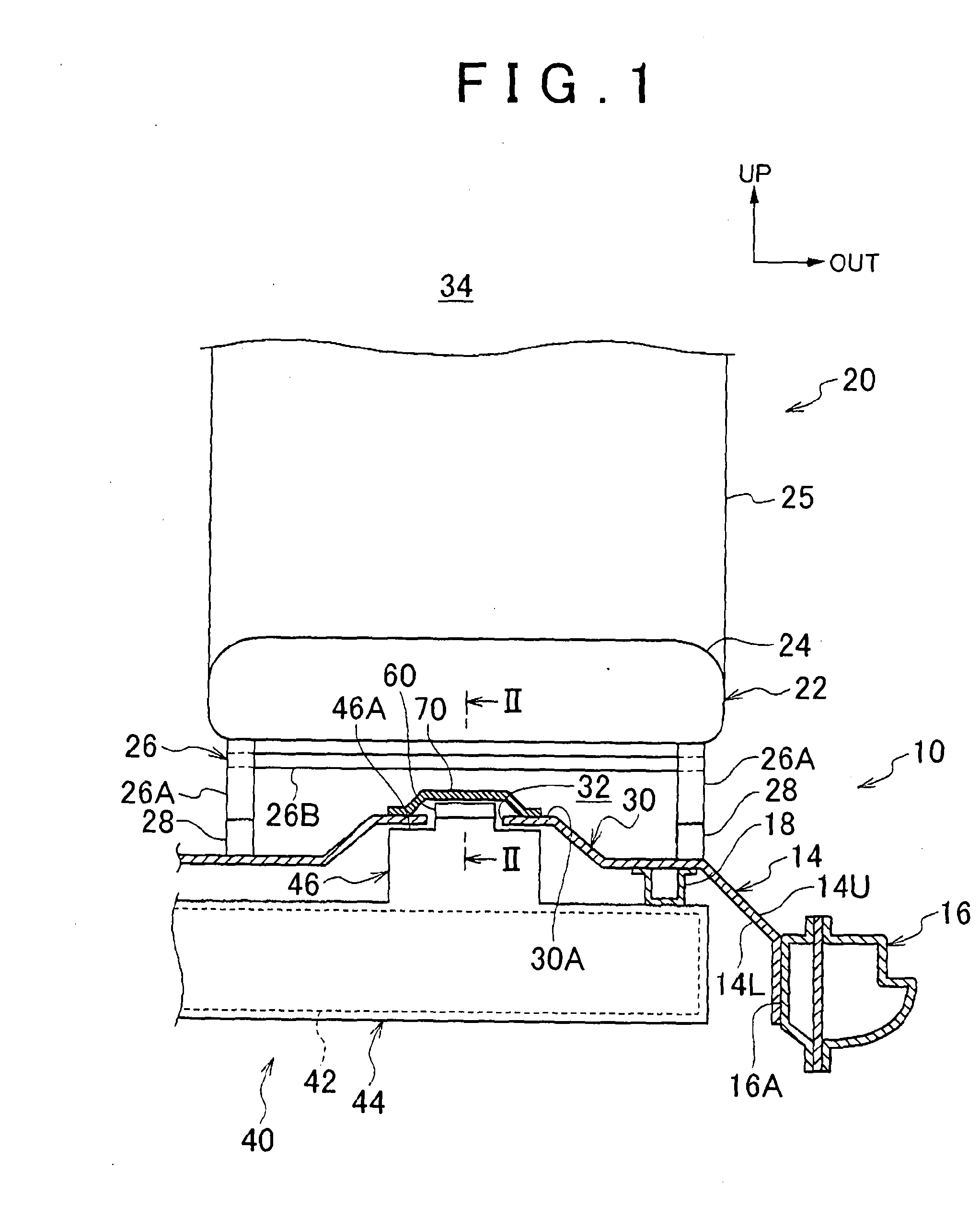
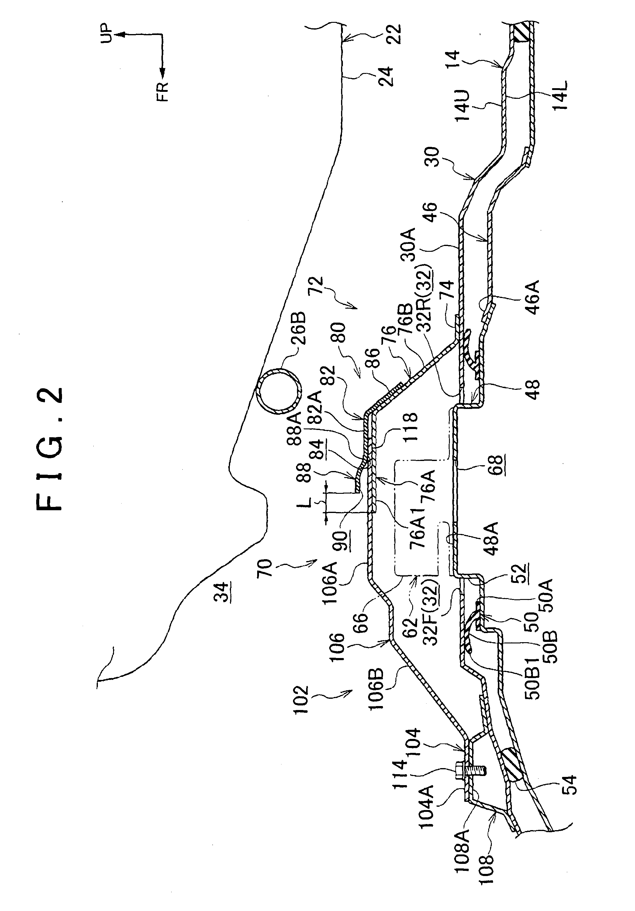
[0033]Hereinafter, a vehicle battery mounting structure according to an embodiment of the invention will be described with reference to the accompanying drawings. Note that an arrow FR shown in the drawing as needed indicates a front side (vehicle front side) in a vehicle longitudinal direction, an arrow UP indicates an upper side in a vehicle vertical direction, and an arrow OUT indicates an outer side in a vehicle width direction.

[0034]FIG. 1 shows a lateral cross-sectional view when a vehicle 12 to which the vehicle battery mounting structure 10 according to the present embodiment is applied is viewed from the front side in the vehicle longitudinal direction. The vehicle 12 may be, for example, an electric vehicle, a gasoline hybrid vehicle, a fuel cell hybrid vehicle, or the like, that is able to travel with the use of an electric motor (motor) (not shown) as a driving source. A battery unit 40 is mounted below a floor panel 14 in the vehicle vertical direction. The floor panel ...


PUM

PropertyMeasurementUnit
electric poweraaaaaaaaaa
workabilityaaaaaaaaaa
poweraaaaaaaaaa

Abstract

A vehicle battery mounting structure having a service hole cover that closes a service hole the service hole cover includes a rear cover that covers a rear end side of the service hole in a vehicle longitudinal direction and a front cover that covers a front end side of the service hole in the vehicle longitudinal direction. That is, the service hole cover is split into the rear cover and the front cover in the vehicle longitudinal direction. The front cover is detachably attached to a floor upper reinforcement provided on a floor panel by bolts.

Description

BACKGROUND OF THE INVENTION[0001]1. Field of the Invention[0002]The invention relates to a vehicle battery mounting structure.[0003]2. Description of Related Art[0004]Japanese Patent Application Publication No. 2009-083601 (JP 2009-083601 A) describes an electric vehicle on which a battery unit having a service plug is mounted below a floor panel. The floor panel of the electric vehicle described in JP 2009-083601 A has a boot mounting hole for operating the service plug, and a cap member that closes the boot mounting hole is fastened by bolts. These boot mounting hole and cap member are located below a front seat.[0005]In addition, Japanese Patent Application Publication No. 2003-341373 (JP 2003-341373 A) describes a power supply unit mounting structure that a power supply unit having a service plug is mounted between a floor panel and a seated portion of a front seat. In the power supply unit mounting structure described in JP 2003-341373 A, a lid that covers the service plug is a...

Claims


Application Information

Patent Timeline
Patent Type & Authority Applications(United States)
IPC IPC(8): B60K1/04H01M2/10B60L50/64
CPCB60K1/04B60K2001/0438H01M2220/20H01M2/1083B60K2001/0422Y02E60/10H01M50/249B60L50/64H01M50/244Y02T10/70Y02T90/14B60R16/04Y02T10/7072
Inventor OGUSHI, HISAYATERAO, YOSHIHITO
Owner TOYOTA JIDOSHA KK
Why Eureka
Try Eureka