Three-level LED bulb microprocessor-based driver

a microprocessor and led bulb technology, applied in the direction of sustainable buildings, energy-efficient lighting, semiconductor lamp usage, etc., can solve the problems of increasing space requirements, increasing costs, and introducing power losses in series components

Inactive Publication Date: 2014-11-06
SWITCH BULB CO INC
View PDF0 Cites 12 Cited by
  • Summary
  • Abstract
  • Description
  • Claims
  • Application Information

AI Technical Summary

Benefits of technology

[0007]A light emitting diode (LED) bulb is described. The LED bulb comprises a shell, a plurality of LEDs within the shell, and a driver circuit. The driver circuit is configured to operate the plurality of LEDs at a plurality of brightness levels. The driver circuit comprises a first input configured to receive alternating current (AC), a second input configured to receive AC, a neutral input, a converter circuit connected to the plurality of LEDs, a first rectifier circuit, a second rectifier circuit, one or more detector circuits, and a signal processing circuit. The first rectifier circuit is connected to the first input and the neutral input. The first rectifier circuit is configured to rectify the AC received at the first input into direct current (DC).

Problems solved by technology

However, this requires having two driver circuits, which increases costs and increases space requirements that are limited when implementing LED bulbs in typical form factors of standard light bulbs.
While this technique may work in pri

Method used


Image

  • Three-level LED bulb microprocessor-based driver
  • Three-level LED bulb microprocessor-based driver
  • Three-level LED bulb microprocessor-based driver

Examples


Embodiment Construction

[0014]The following description is presented to enable a person of ordinary skill in the art to make and use the various embodiments. Descriptions of specific devices, techniques, and applications are provided only as examples. Various modifications to the examples described herein will be readily apparent to those of ordinary skill in the art, and the general principles defined herein may be applied to other examples and applications without departing from the spirit and scope of the various embodiments. Thus, the various embodiments are not intended to be limited to the examples described herein and shown, but are to be accorded the scope consistent with the claims.

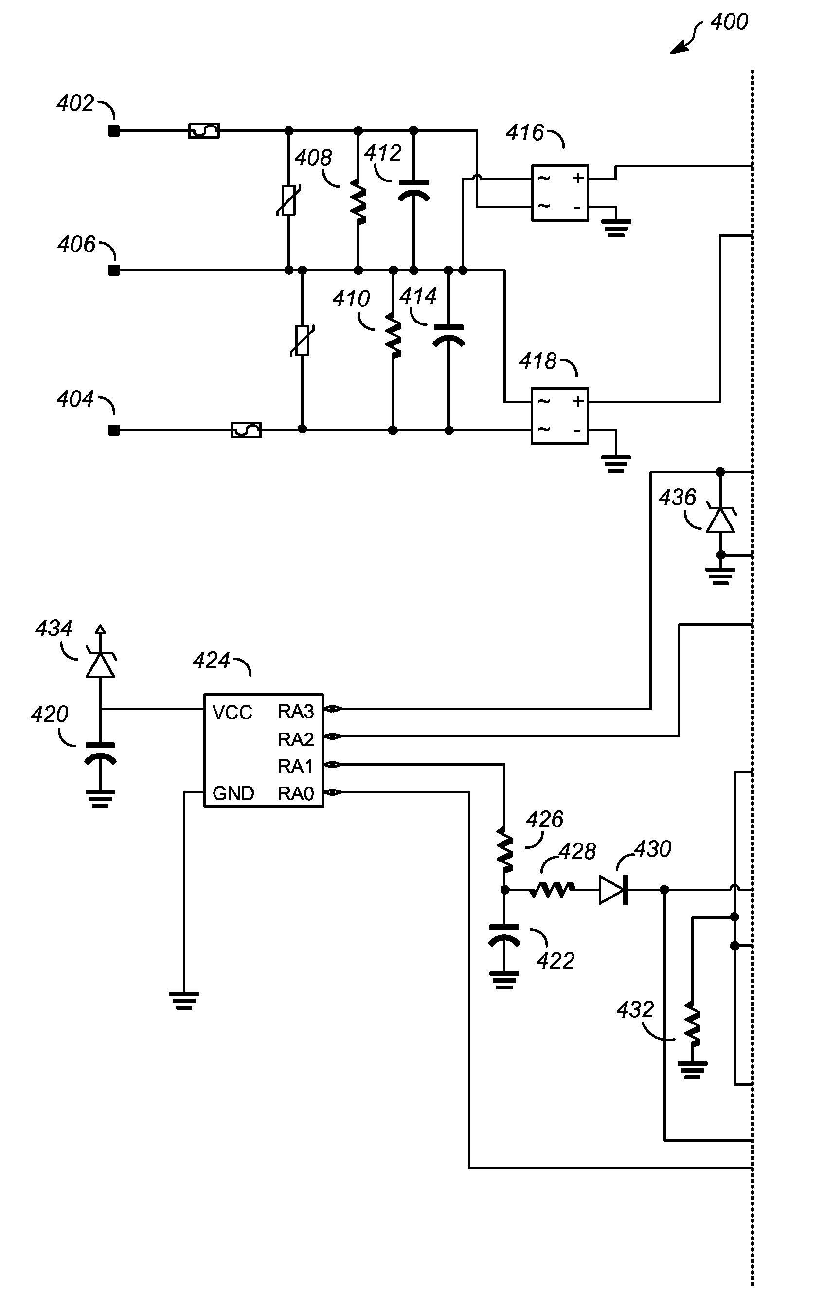
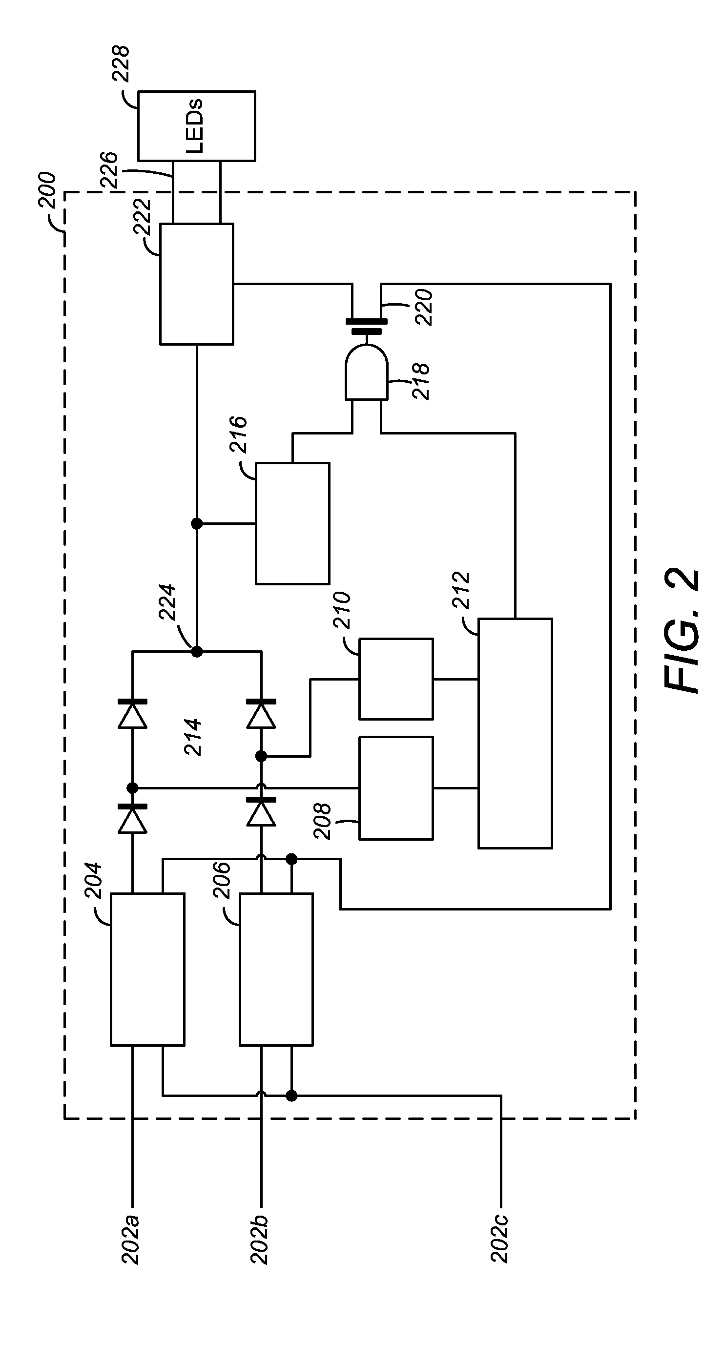
[0015]An exemplary LED driver circuit that can drive one or more LEDs at three different brightness levels by driving the LEDs at three different currents is described below. The driver circuit uses a microcontroller to sense the input line voltages from a three-way switch. This reduces the number of required parts. Acc...


PUM


Abstract

An LED bulb is described, comprising LEDs within a shell and a driver circuit to operate the LEDs at a plurality of brightness levels. The driver circuit comprises first and second inputs to receive AC, a neutral input, a converter circuit, first and second rectifier circuits, a detector circuit, and a processing circuit. The first rectifier circuit is connected to the first and neutral inputs and rectifies the AC received. The second rectifier circuit is connected to the second and neutral inputs and rectifies the AC received. The detector circuit is connected to the first and second rectifier circuits. The processing circuit has a first and a second processor input, and is connected to the detector circuit. The processing circuit produces a chop signal with a duty cycle based on whether the first or second input is hot. The converter circuit powers the LEDs based on the chop signal.

Description

BACKGROUND[0001]1. Field[0002]The present disclosure relates generally to microprocessor-based drivers for light emitting diode (LED) bulbs, and more specifically to microprocessor-based drivers for LED bulbs that enable the LED bulb to emit light at different levels of brightness.[0003]2. Description of Related Art[0004]Conventional incandescent light bulbs that have three lighting levels (“three-way light bulbs”) include two filaments; in the minimum illumination setting a low wattage filament is energized, in the medium illumination setting a medium wattage filament is energized, in the high illumination setting both filaments are energized. The illumination setting is selected by energizing a first input connected to the low wattage filament, energizing a second input connected to the medium filament, or energizing both the first and second inputs.[0005]The conventional incandescent three-way light bulb has three electrical contacts, hot1, hot2, and neutral. A switch, contained ...

Claims


Application Information

Patent Timeline
IPC IPC(8): H05B33/08H05B44/00
CPCH05B33/0845H05B45/10Y02B20/00Y02B20/30H05B45/3725H05B45/375H05B45/385H05B45/14
Inventor WENDT, ROLF
Owner SWITCH BULB CO INC
Why Eureka
Try Eureka