Mobile station apparatus, communication system, communication method, and integrated circuit

a mobile station and communication system technology, applied in power management, orthogonal multiplex, multiplex communication, etc., can solve problems such as the estimation of path loss of the mobile station apparatus, and achieve the effect of efficient transmission of signals in the uplink

Inactive Publication Date: 2014-11-06
SHARP KK
View PDF1 Cites 70 Cited by
  • Summary
  • Abstract
  • Description
  • Claims
  • Application Information

AI Technical Summary

Benefits of technology

[0031]The present invention makes it possible for a base station apparatus to co...

Problems solved by technology

More specifically, the mobile station apparatus estimates a pa...

Method used


Image

  • Mobile station apparatus, communication system, communication method, and integrated circuit
  • Mobile station apparatus, communication system, communication method, and integrated circuit
  • Mobile station apparatus, communication system, communication method, and integrated circuit

Examples


first embodiment

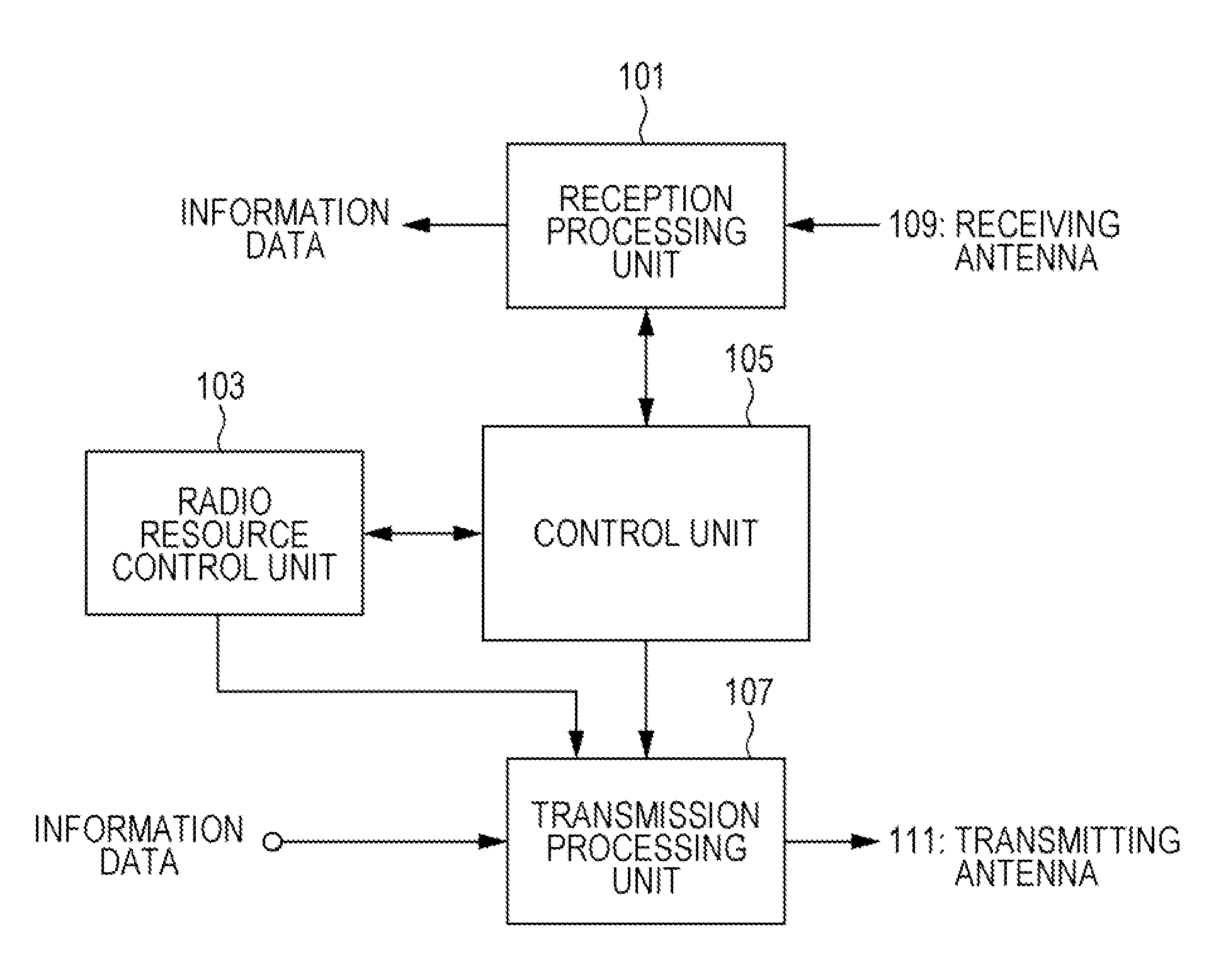
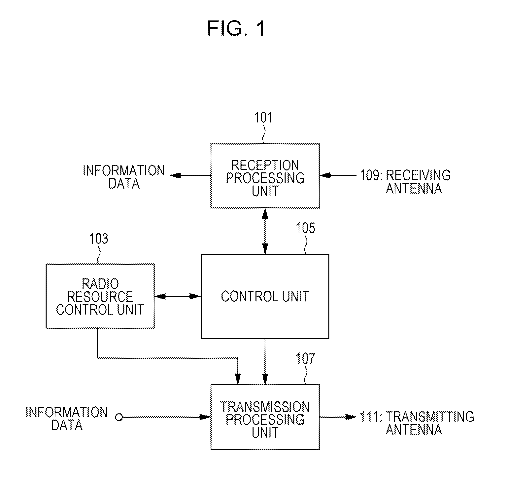
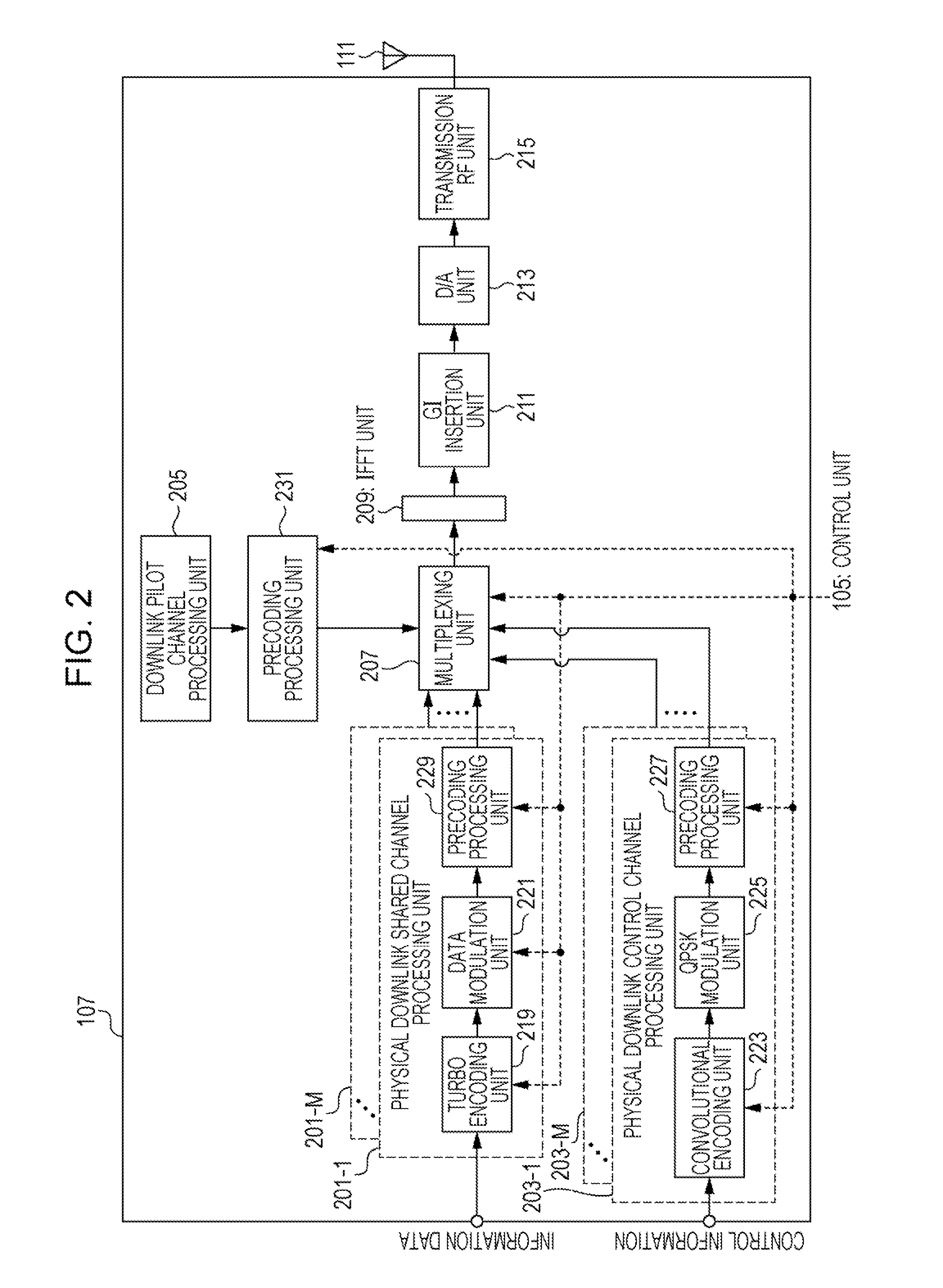
[0045]A first embodiment of the present invention is described in detail below with reference to drawings. First, referring to FIG. 8 to FIG. 12, an overview of a communication system according to the present embodiment is given, and a configuration of a radio frame is discussed. Next, referring to FIG. 1 to FIG. 6, a configuration of the communication system according to the present embodiment is described. Thereafter, referring to FIG. 7, an operation and processing associated with the communication system according to the present embodiment are described.

[0046]FIG. 8 is a diagram illustrating an overview of a communication system according to an embodiment of the present invention. In the communication system 1 illustrated in this figure, communication is performed among a base station apparatus (also referred to as eNodeB, NodeB, BS (Base Station), AP (Access Point), or macro base station) 3, a plurality of RRHs (Remote Radio Heads, which are apparatuses being smaller in size th...

second embodiment

[0194]A second embodiment of the present invention is different from the first embodiment in downlink reference signals used in measurement of a plurality of path losses. In the second embodiment, each of the plurality of path losses is calculated based on a CSI-RS, and more specifically respective path losses are calculated based on CSI-RSs (first reference signal, second reference signal) corresponding to different antenna ports. The mobile station apparatus 5 receives, from the base station apparatus 3 or the RRH 4, a notification specifying antenna ports (including a plurality of antenna ports) associated with the CSI-RSs used in the measurement of the respective path losses. Part of the CSI-RSs is transmitted only from an antenna port of the base station apparatus 3, while part of the CSI-RSs is transmitted only from the RRH 4. According to the specifications by the base station apparatus 3 and the RRH 4, the mobile station apparatus 5 calculates one path loss based on the CSI-...


PUM


Abstract

A base station apparatus efficiently controls transmission of an uplink signal to a mobile station apparatus. A transmission power setting unit sets transmission power for a physical uplink shared channel using one of a plurality of calculated path losses. A power headroom generation unit generates a first power headroom and a second power headroom, wherein the first power headroom is information associated with a margin of transmission power and produced using a band width of a resource allocated for the physical uplink shared channel and the path loss used in the setting of the transmission power for the physical uplink shared channel, and the second power headroom is information associated with a margin of transmission power and produced, without depending on the band width of the resource allocated for the physical uplink shared channel, using a path loss that is one of the plurality of calculated path losses but that is not used in the setting of the transmission power for the physical uplink shared channel.

Description

TECHNICAL FIELD[0001]The present invention relates to a mobile station apparatus capable of efficiently transmitting a signal in an uplink in a communication system including a plurality of mobile station apparatuses and a base station apparatus, and also relates to a communication system, a communication method, and an integrated circuit.BACKGROUND ART[0002]Specifications of cellular mobile communication in terms of a wireless access method and an advanced wireless network (hereinafter referred to as Long Term Evolution (LTE) or Evolved Universal Terrestrial Radio Access (EUTRA)) has been established by the 3rd Generation Partnership Project (3GPP). In LTE, orthogonal frequency division multiplexing (OFDM), which is a multi-carrier transmission method, is used as a communication method for wireless communication from a base station apparatus to a mobile station apparatus (referred to as a downlink (DL)). Furthermore, in LTE, SC-FDMA (Single-Carrier Frequency Division Multiple Acces...

Claims


Application Information

Patent Timeline
IPC IPC(8): H04W52/36
CPCH04W52/365H04J11/0053H04L5/0035H04L5/0044H04L5/0046H04W52/242H04W52/325
Inventor NAKASHIMA, DAIICHIROOUCHI, WATARUSUZUKI, SHOICHIIMAMURA, KIMIHIKO
Owner SHARP KK
Why Eureka
Try Eureka