Hazardous-rated exit sign and floodlights

a technology of floodlights and exit signs, applied in the direction of signs, display means, instruments, etc., can solve the problems of affecting the integrity of explosion-proof fixtures, requiring maintenance and upkeep, and incandescent lamps being subject to burnou

Active Publication Date: 2014-11-13
RIG A LITE PARTNERSHIP
View PDF2 Cites 10 Cited by
  • Summary
  • Abstract
  • Description
  • Claims
  • Application Information

AI Technical Summary

Benefits of technology

[0014]An object of the invention is to provide an exit sign suitable for use in areas with a hazardous or potentially hazardous atmosphere which uses a long-life low-powered non-incandescent light source for maximum reliability.

Problems solved by technology

Inevitably, the incandescent lamps are subject to burn out, requiring maintenance and upkeep.
A relamping tool is generally required to replace the light bulbs, and should the maintenance person fail to properly seal the exit sign after lamp replacement, explosion-proof integrity may be compromised.
Further, the explosion-proof exit signs known in the art do not have an integral battery back-up or other source of redundant power to keep the signs illuminated during power failures.
The separate circuit(s) required for exit signs results in increased facility construction costs.
Still further, explosion-proof signs known in the art do not provide adequate or additional illumination of a point of exit from a building, which may impede safe and fast egress from a building in the event of an emergency or power outage.

Method used


Image

  • Hazardous-rated exit sign and floodlights
  • Hazardous-rated exit sign and floodlights
  • Hazardous-rated exit sign and floodlights

Examples


Embodiment Construction

[0027]The aspects, features, and advantages of the invention mentioned above are described in more detail by reference to the drawings, wherein like reference numerals represent like elements.

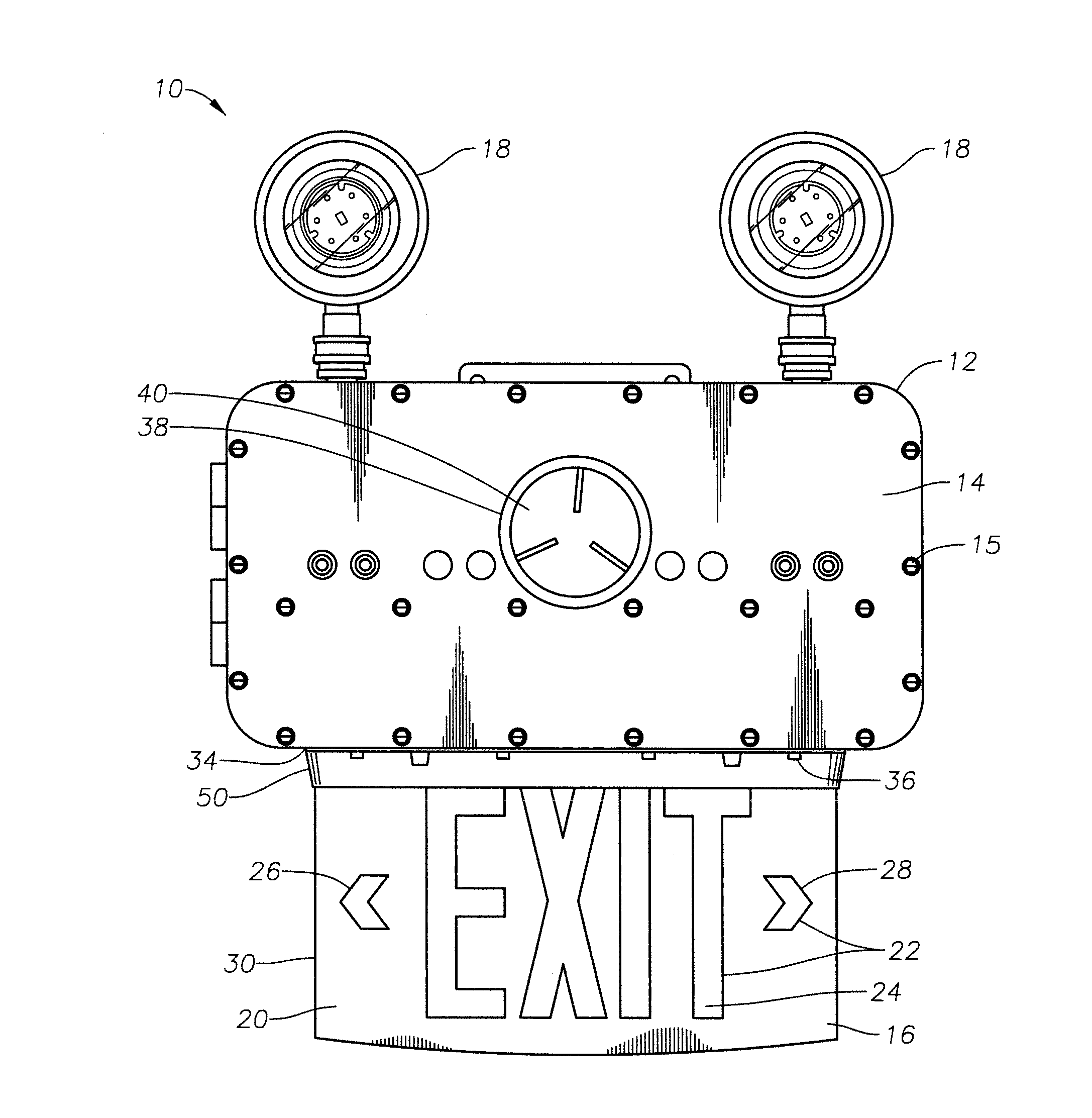
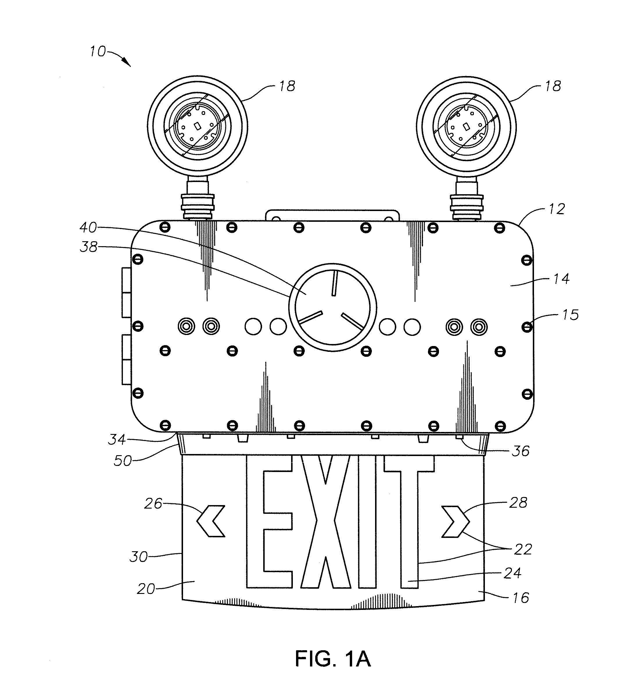
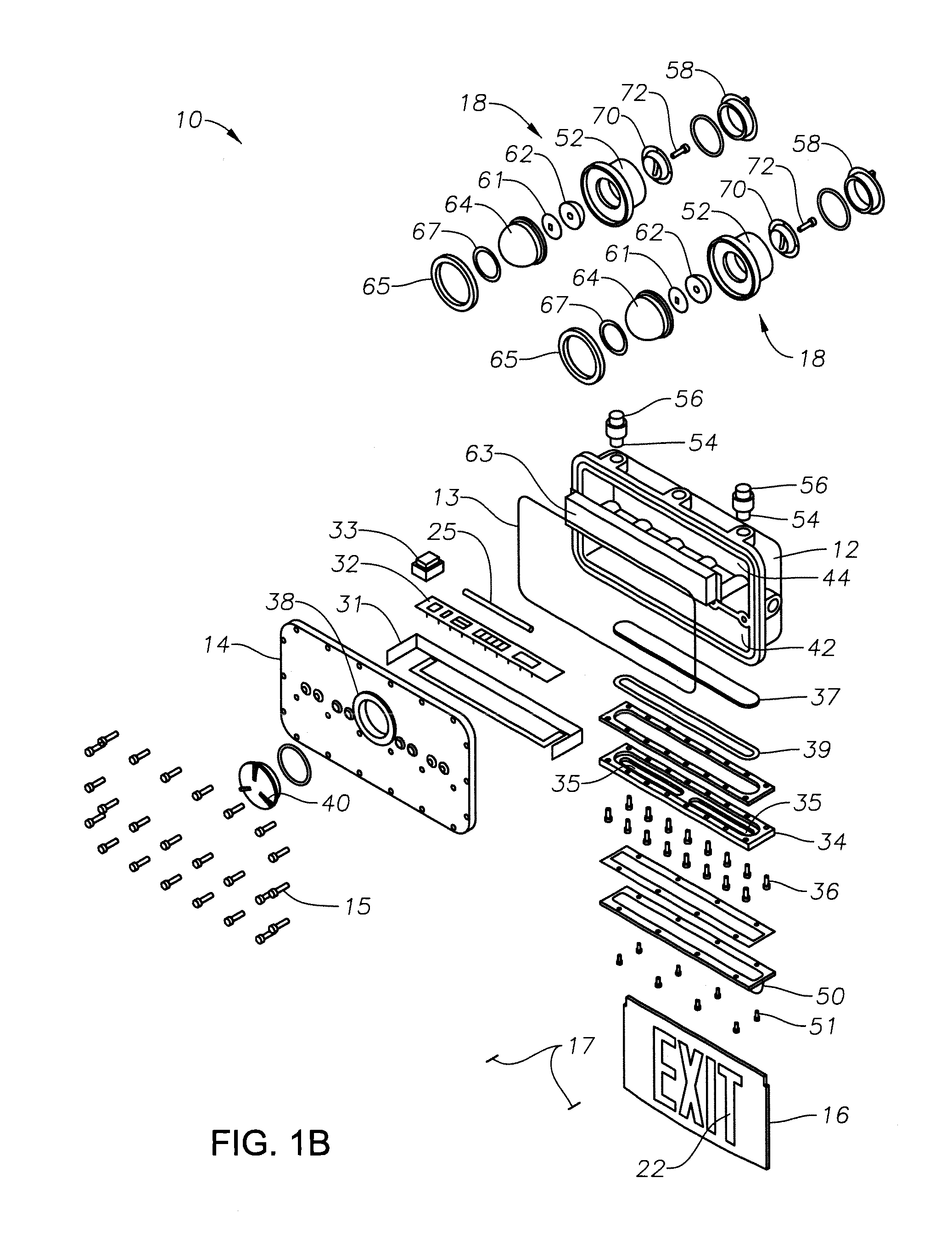
[0028]Referring to FIGS. 1A, 1B and 2, an exit sign 10 suitable for use in locations deemed hazardous due to the presence or potential presence of flammable vapors or gases or combustible dusts in accordance with one or more embodiments of the present disclosure is shown. Exit sign 10 may be designed and arranged to be certified for use in NEC Class I Division 1 and 2, Groups B, C and D, Class I Zone 1 Group IIB, and Class II Division 1 Groups E, F and G. In addition, exit sign 10 may also be certified for use in Class I Zones 0, 1 and 2 Groups IIA, JIB plus hydrogen, and TIC areas. Still further, exit sign 10 may also be certified for use in Class III areas. Exit sign 10 preferably complies with UL Standard 844. UL Standards 844, 1604 and 2279 are incorporated herein by reference. The exit sig...


PUM


Abstract

An exit sign includes an explosion-proof housing having a first chamber and a second chamber within the housing separated by a divider wall, a bottom plate attached to said housing and defining an interface between said housing and said bottom plate, and a window, disposed in said bottom plate, containing a clear glass or plastic window pane and located proximate to said first chamber of said housing, wherein a volume of said first chamber, a housing wall thickness surrounding said first chamber, a divider wall thickness, and a window pane thickness are arranged and designed according to an expected internal explosion pressure within said first chamber, and wherein a volume of said second chamber, a housing wall thickness surrounding said second chamber, and a divider wall thickness are arranged and designed according to an expected internal explosion pressure within said second chamber. The exit sign includes a generally planar sign panel coupled to said housing at said window, an indicium disposed on said sign panel, a plurality of light emitting diodes disposed within said second chamber of said housing and directed to shine light through said window into said sign panel, and at least one floodlight comprising one or more light emitting diodes directed to illuminate a region in proximity with said exit sign.

Description

BACKGROUND OF THE INVENTION[0001]1. Field of the Invention[0002]This invention relates generally to hazardous-location-rated fixtures and specifically to illuminated exit signs.[0003]2. Description of the Prior Art[0004]Fixtures for use within hazardous locations are well known. In the 1920s, the National Electric Code (NEC) addressed requirements for fixtures to be located in rooms or compartments in which highly flammable gases, liquids, mixtures or other substances were manufactured, used or stored. In 1931, the NEC first defined hazardous location classifications Class I for gases and vapors, Class II for dusts, and Class III / Class IV for fibers. Four years later, the NEC subdivided Class I locations into groups based on explosive pressure and flame transmission capacity. Group A includes acetylene. Group B includes hydrogen. Group C includes ethyl ether, and Group D includes gasoline, petroleum, alcohol, acetone, solvent vapors, and gases and vapors of equivalent hazard. Likewi...

Claims


Application Information

Patent Timeline
Patent Type & Authority Applications(United States)
IPC IPC(8): G09F13/04G09F13/06
CPCG09F13/0413G09F13/06G09F2013/0445G08B7/062G09F13/18G09F2007/1843G09F2007/186G09F2013/1872G09F2013/222G09F13/049G09F2013/05G09F13/0445
Inventor HASAN, SYED Q.
Owner RIG A LITE PARTNERSHIP
Why Eureka
Try Eureka