Mechanical connection forming a pivot for MEMS and nems mechanical structures

a mechanical structure and pivot technology, applied in the direction of microstructural technology, acceleration measurement using interia forces, piezoelectric/electrostrictive devices, etc., can solve the problems of generating undesired movements of the mems or nems structure, mechanical strain can damage the mems structure, and beams that do not enable all the amplitudes of translation movements to be reduced

Active Publication Date: 2014-11-13
COMMISSARIAT A LENERGIE ATOMIQUE ET AUX ENERGIES ALTERNATIVES
View PDF5 Cites 27 Cited by
  • Summary
  • Abstract
  • Description
  • Claims
  • Application Information

AI Technical Summary

Benefits of technology

[0017]Consequently, one object of the present invention is to offer a pivot connection for MEMS and NEMS structures enabling any MEMS or NEMS structures proofed against mechanical disturbances to be made.

Problems solved by technology

If the magnetic field has a high intensity, the mechanical strain can damage the MEMS structure.
These forces can generate undesired movements of the MEMS or NEMS structure.
Yet, a pivot connection formed by bending beams or torsion beams does not enable all the amplitudes of the translation movements to be reduced along the three spatial directions and the rotation movements about directions orthogonal to the axis of the pivot connection.
In other words, a pivot connection exclusively formed by either type of beam does not ensure high stiffnesses according to these degrees of freedom.
However, the reduction of the transverse cross-sections of these beams strongly decreases their transverse stiffnesses.
These interference displacements can occur in the signal delivered by the sensor.
Measurement methods enable this interference signal to be reduced by virtue of the placement, for example, of bridges of capacitances having opposite dependencies, however the measurement methods are made more complex.
These high stiffnesses along the three directions can raise problem in case of impact, because the elements having the highest stiffnesses are precisely the ones which oppose the forces generated by the impact: as a result, there is an increased risk of degradation of the gauges and connection elements with lower dimensions than those of beams forming the pivot, and thus an increased risk of degradation of the MEMS or NEMS.
Because of their high longitudinal and transverse stiffnesses, the gauges can block interfering movements, however they can, by way of compensation, be subjected to high and destructible strains.
For example, in case of an impact lower than 10000 g, which is a usually used value, the gauges could be damaged and consequently, the system would become out of service.
However, this solution does not enable to solve the problem raised in any circumstance.
The movements performed during a damage can have amplitudes much lower than one micrometer, which is the limit below which etching the spacings between the stop and the movable structure becomes difficult.

Method used


Image

  • Mechanical connection forming a pivot for MEMS and nems mechanical structures
  • Mechanical connection forming a pivot for MEMS and nems mechanical structures
  • Mechanical connection forming a pivot for MEMS and nems mechanical structures

Examples


Embodiment Construction

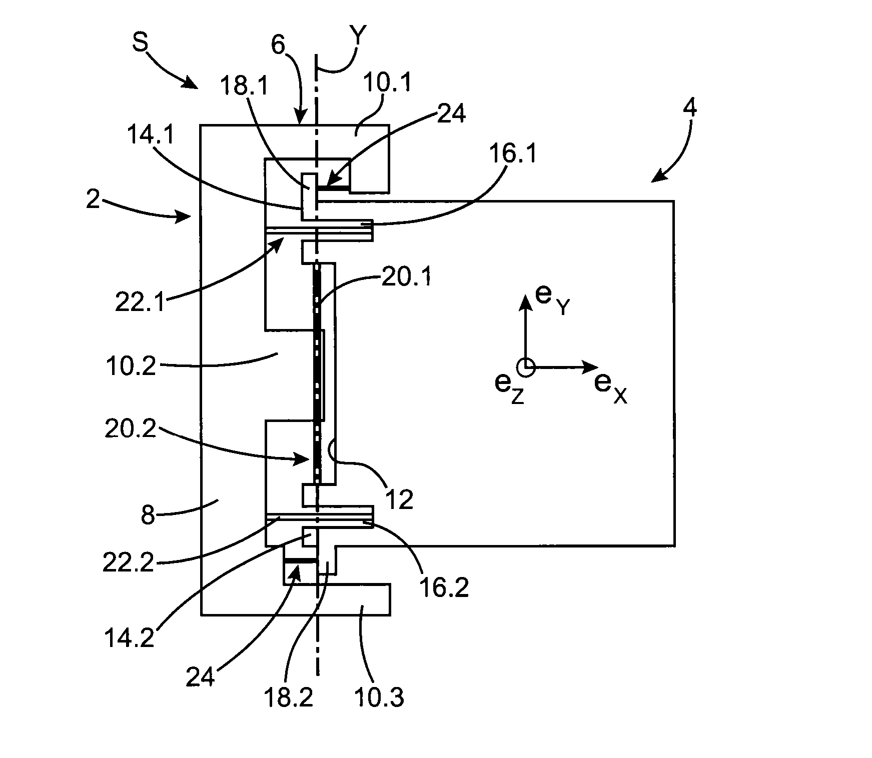
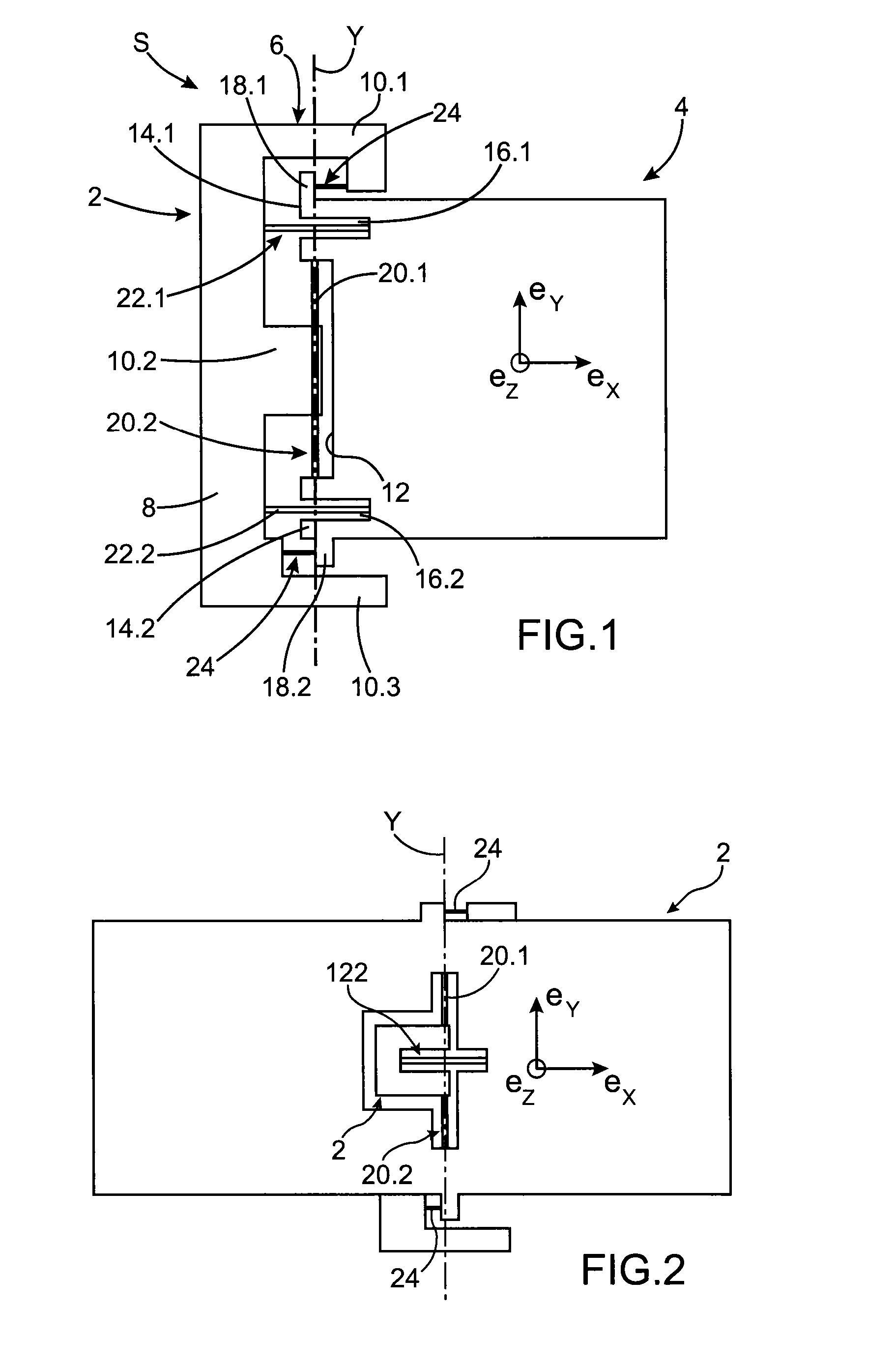
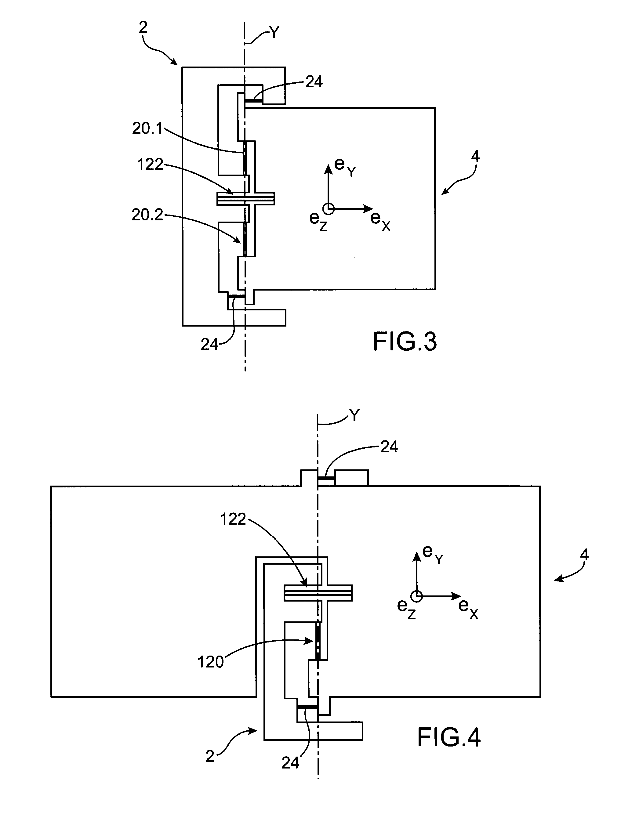
[0051]In the description that follows, the three directions ex, ey, ez will be considered orthogonal with respect to each other. Y designates the axis of the pivot connection according to the present invention, extending along the direction ey.

[0052]In FIG. 1, can be distinguished a MEMS or NEMS structure S comprising a fixed part 2, for example a substrate, a movable part 4 suspended with respect to the fixed part 2 and a pivot connection 6 with an axis Y connecting the fixed part 2 and the movable part. The axis Y will be designated “pivot axis” in the rest of the description.

[0053]The fixed part 2 could also be itself movable with respect to another part of the structure.

[0054]In the particular example represented in FIG. 1, the fixed part 2 comprises a main body 8 extending longitudinally substantially parallel to the axis Y and three legs 10.1, 10.2, 10.3 perpendicular to the main body 8, such that, when viewed from above, the fixed part is substantially E shaped.

[0055]The mova...


PUM


Abstract

A mechanical connection between two parts of a microelectromechanical and/or nanoelectromechanical structure forming a pivot with an axis of rotation pivot includes two first beams with an axis parallel to the pivot axis, the first beams configured to work in torsion, and two second beams with an axis orthogonal to the axis of the first beams, the second beams configured to work in bending, each one of the first and second beams being connected at their ends to the two parts of the structure.

Description

TECHNICAL FIELD AND PRIOR ART[0001]The present invention relates to a pivot forming mechanical connection for MEMS (“microelectromechanical systems”) and NEMS (“nanoelectromechanical systems”) structures between two parts able to pivot with respect to each other.[0002]In the state of the art, there are two technical solutions to make a pivot connection in MEMS and NEMS structures.[0003]The first solution implements beams connecting for example the fixed part and the movable part and working in bending. The beams are provided in parallel to each other, and the axis of the pivot connection is orthogonal to the axis of the beams.[0004]The second solution implements aligned beams, for example two in number, connecting the fixed part and the movable part, and working in torsion. The axis of the pivot connection and the axis of the beams are coincident.[0005]MEMS and NEMS structures, for example used as a gyrometer or an accelerometer, use the movable part, being moved by a Coriolis force...

Claims


Application Information

Patent Timeline
Patent Type & Authority Applications(United States)
IPC IPC(8): F16C11/04G01P15/02B81B3/00
CPCF16C11/04B81B3/00G01P15/02B81B3/0051B81B2203/0154B81B2203/058Y10T403/32606
Inventor JOURDAN, GUILLAUMEETTELT, DIRKREY, PATRICEWALTHER, ARNAUD
Owner COMMISSARIAT A LENERGIE ATOMIQUE ET AUX ENERGIES ALTERNATIVES
Why Eureka
Try Eureka