
Pneumatic tire

a technology of pneumatic tires and treads, which is applied in the field of pneumatic tires, can solve the problems of unavoidable shape change of pneumatic tires, and achieve the effects of reducing the generation of uneven tread wear, reducing the generation of cracks in the groove bottom, and facilitating evaluation of the durability of pneumatic tires

Active Publication Date: 2014-11-13
SUMITOMO RUBBER IND LTD
View PDF8 Cites 2 Cited by
  • Summary
  • Abstract
  • Description
  • Claims
  • Application Information

AI Technical Summary

Benefits of technology

The present invention relates to a pneumatic tire with reduced cracks in the grove bottoms and less uneven wear of the tread, as well as an easy-to-use test method to evaluate the tire's durability. The designing method ensures that the tire has excellent durability.

Problems solved by technology

The change of the shape is unavoidable in pneumatic tires.

Method used


Image

  • Pneumatic tire
  • Pneumatic tire
  • Pneumatic tire

Examples


example 1

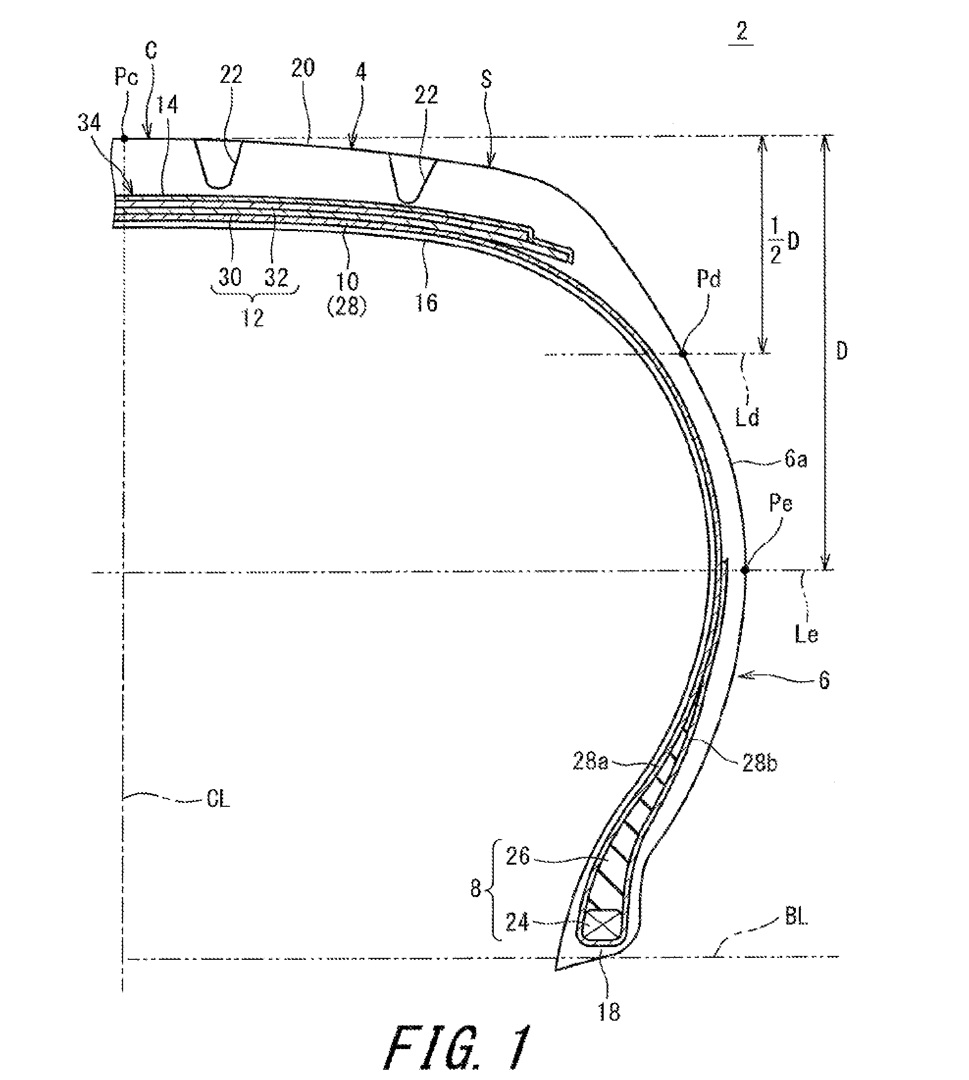
[0112]A tire having the fundamental structure shown in FIG. 1 was produced as a sample tire. The size of the tire was “185 / 70R14”. Namely, the nominal width W of the tire was 185 (mm), and the aspect ratio A thereof was 70%. The tire was mounted to a normal rim of 14×5.5J. The tire was inflated with air to an internal pressure of 12 kPa. Thereafter, the tire was inflated with air to the normal internal pressure of 240 kPa. For the tire, the amount of protrusion Dd (mm), the amount of protrusion De (mm), the value Fe of difference in the amount of protrusion, and the value Fa of the sum of the amounts of protrusions, were obtained. The results are indicated in Table 1.

example 5

[0114]A tire having the fundamental structure shown in FIG. 4 was produced as a sample tire. The size of the tire was “225 / 40R18”. Namely, the nominal width W of the tire was 225 (mm), and the aspect ratio A thereof was 40%. The tire was mounted to a normal rim of 18×8J. The tire was inflated with air to an internal pressure of 12 kPa. Thereafter, the tire was inflated with air to the normal internal pressure of 240 kPa. For the tire, the amount of protrusion Dd (mm), the amount of protrusion De (mm), the value Fs of difference in the amount of protrusion, and the value Fa of the sum of the amounts of protrusions, were obtained. The results are indicated in Table 2.

example 10

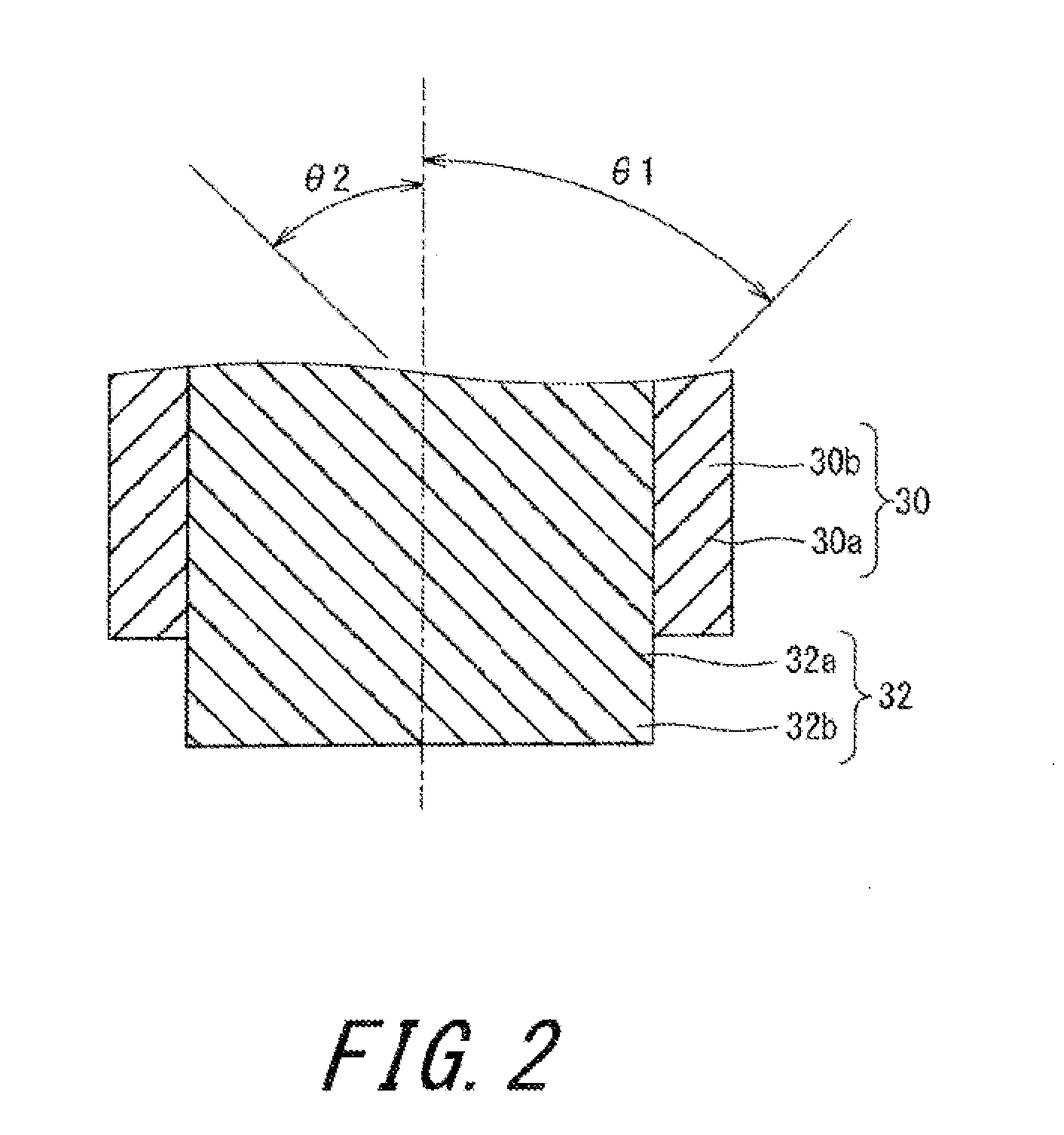
[0116]A tire having the fundamental structure shown in FIG. 1 was produced as a sample tire. The size of the tire was “185 / 70R14”. In the tire, the cords of the inner layer of the belt and the cords of the outer layer of the belt were inclined relative to the equator plane in the directions opposite to each other. The absolute value θ of the inclination angle of each cord was 22.5°. The tire was mounted to a normal rim of 14×5.5J. The tire was inflated with air to an internal pressure of 12 kPa. Thereafter, the tire was inflated with air to the normal internal pressure of 240 kPa. For the tire, the amount of protrusion Dd (mm), the amount of protrusion Do (mm), the value Fs of difference in the amount of protrusion, and the value Fa of the sum of the amounts of protrusions, were obtained. The results are indicated in Table 3.


PUM

PropertyMeasurementUnit
widthaaaaaaaaaa
internal pressureaaaaaaaaaa
pressureaaaaaaaaaa

Abstract

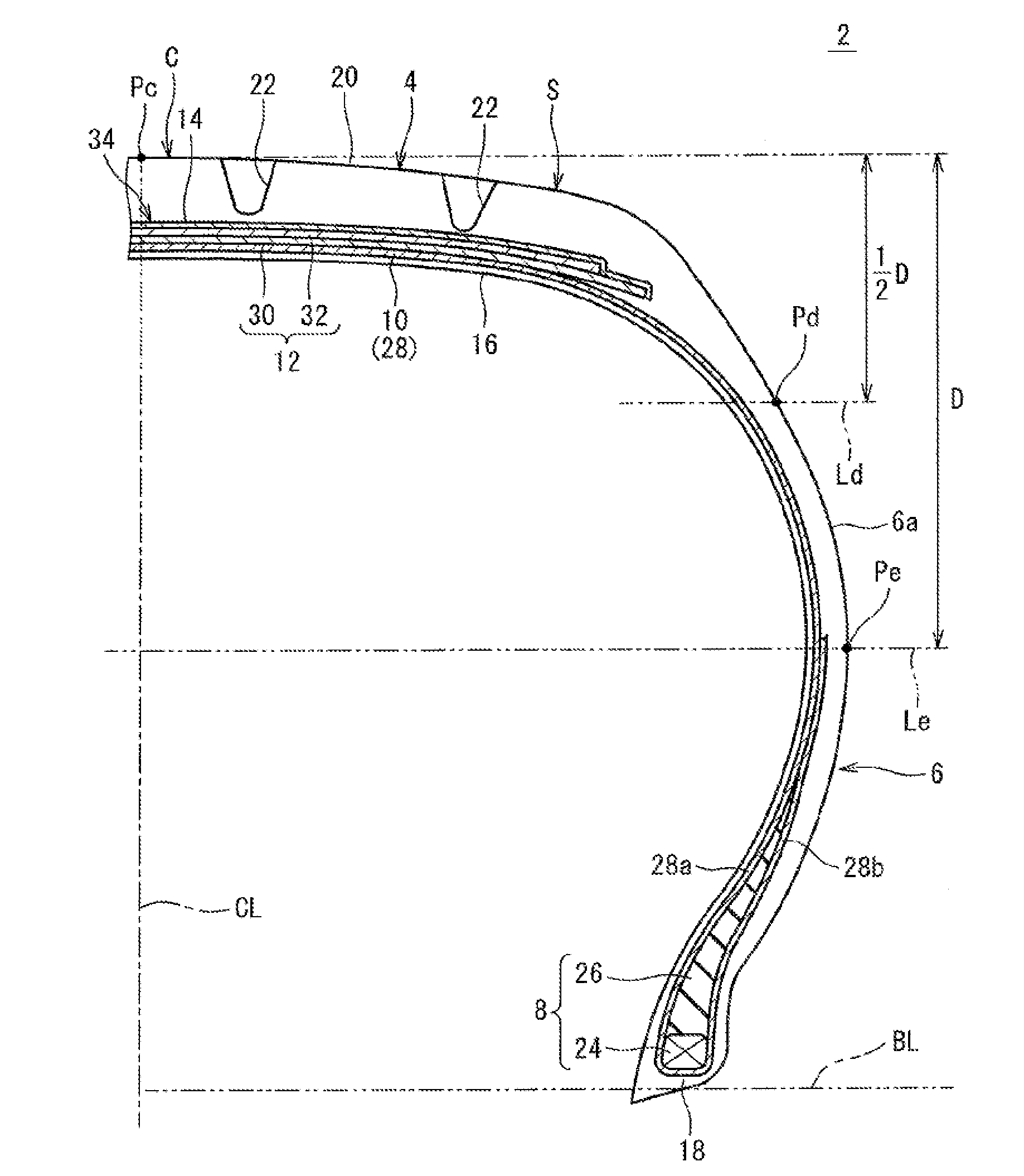
A pneumatic tire excellent in resistance to uneven wear, and crack resistance of a groove is provided. A position, on an equator plane, of a tread surface 20 of a tire 2 is represented as a point Pc. A position, at a maximum width, of an axially outer side surface 6a of a sidewall 6 is represented as a point Pe. A position that is a mid-point, in the radial direction, between the point Pc and the point Pe, and that is on the axially outer side surface 6a, is represented as a point Pd. When an internal pressure is enhanced from an Internal pressure that is 0.05 times a normal internal pressure P to the normal internal pressure P, a value Fs of difference in amount of protrusion between an amount of protrusion Dd (mm) at the point Pd and an amount of protrusion De (mm) at the point Pe is calculated according to mathematical expression (1) in which a nominal width is represented as W (mm). The value Fs of difference in amount of protrusion is greater than −0.4 and less than 0.5.Fs=((Dd−De) / W)×100  (1)

Description

TECHNICAL FIELD[0001]The present invention relates to pneumatic tires.BACKGROUND ART[0002]Various pneumatic tires that include treads having improved wear resistance and various pneumatic tires in which tread surfaces include grooves having improved crack resistance and durability, have been suggested.[0003]In JP2-106404, a pneumatic tire is suggested in which a radius of curvature of a tread, and an amount of protrusion of the tread in the case of the tire being inflated with air are specified to improve crack resistance and durability of grooves of the tread surface. For this tire, it is suggested that a difference between an amount of protrusion at the center of the tread and an amount of axially outward protrusion of the tread is set so as to be within a predetermined range. In this tire, change of an amount of protrusion of the tread and change of the radius of curvature of the tread are reduced when a low internal pressure state shifts to a standard internal pressure state.[00...

Claims


Application Information

Patent Timeline
Patent Type & Authority Applications(United States)
IPC IPC(8): B60C9/20G01M17/02G01N3/56B29D30/06B60C11/03
CPCB60C9/20B29D30/0601B60C11/03G01N3/56G01M17/022B29D2030/0665B60C2009/2012B60C9/0292B60C13/003B60C19/00
Inventor ASANO, KAZUOTOMITA, SHINTAROTANAKA, SUSUMU
Owner SUMITOMO RUBBER IND LTD
Learn More