Insert for a tube for dispensing liquid content and tube with such an insert

Active Publication Date: 2014-11-13
HOFFMANN NEOPAC
View PDF0 Cites 1 Cited by
  • Summary
  • Abstract
  • Description
  • Claims
  • Application Information

AI Technical Summary

Benefits of technology

[0020]The insert of the invention has the advantage that it can be inserted into the tube and its spout, respectively, from the distal end of the tube, which simplifies manufacturing. For ease of mounting the insert of the invention is preferably symmetrical along its longitudinal axis, such that mounting is also possible if the insert is not exactly aligned with the spout for insertion. Furthermore, the insert according to the invention is preferably symmetrical along its transverse axis, so that it does not matter which way the insert is held during mounting and mounting is even more facilitated.
[0021]As the mounting of the insert is performed in the inside of the tube, additional sealing surfaces towa

Problems solved by technology

With conventional tubes it is often not possible to dispense liquids in the form of drops, even if the liquids are principally able to form drops.
Instead the liquid is often dispensed in the form of a jet or spurt, which makes precise dosing of the liquid difficult.
With some conventional tubes drop-dispensing might be possible, if a user only applies very light pressure to the tube body, which, however, can impair ease of application and user-friendliness.
With this rather small diameter of the opening and the rather large lengt

Method used


Image

  • Insert for a tube for dispensing liquid content and tube with such an insert
  • Insert for a tube for dispensing liquid content and tube with such an insert
  • Insert for a tube for dispensing liquid content and tube with such an insert

Examples


Example

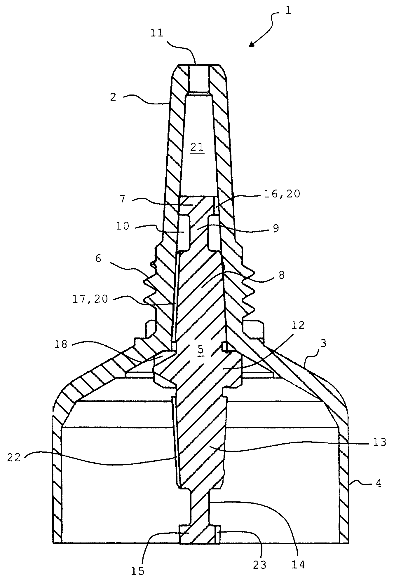
[0027]FIG. 1 shows a tube 1 according to the invention with an elongated spout 2, a tube shoulder 3, a tube body 4 and an insert 5 according to the invention, the insert 5 being mounted inside the tube 1. For simplicity of presentation the part of the tube body 4 that lies below the insert 5 has been omitted, with “below” referring to the representation in FIG. 1. The spout 2 is preferably formed as cannula for more accurate application of the drops to be dispensed. On its outer wall the spout 2 comprises threads 6 to engage with threads of a cap (not shown) that can be placed onto the spout 2. At its proximal end the spout 2 has an orifice 11 trough which liquid can be dispensed as drops.

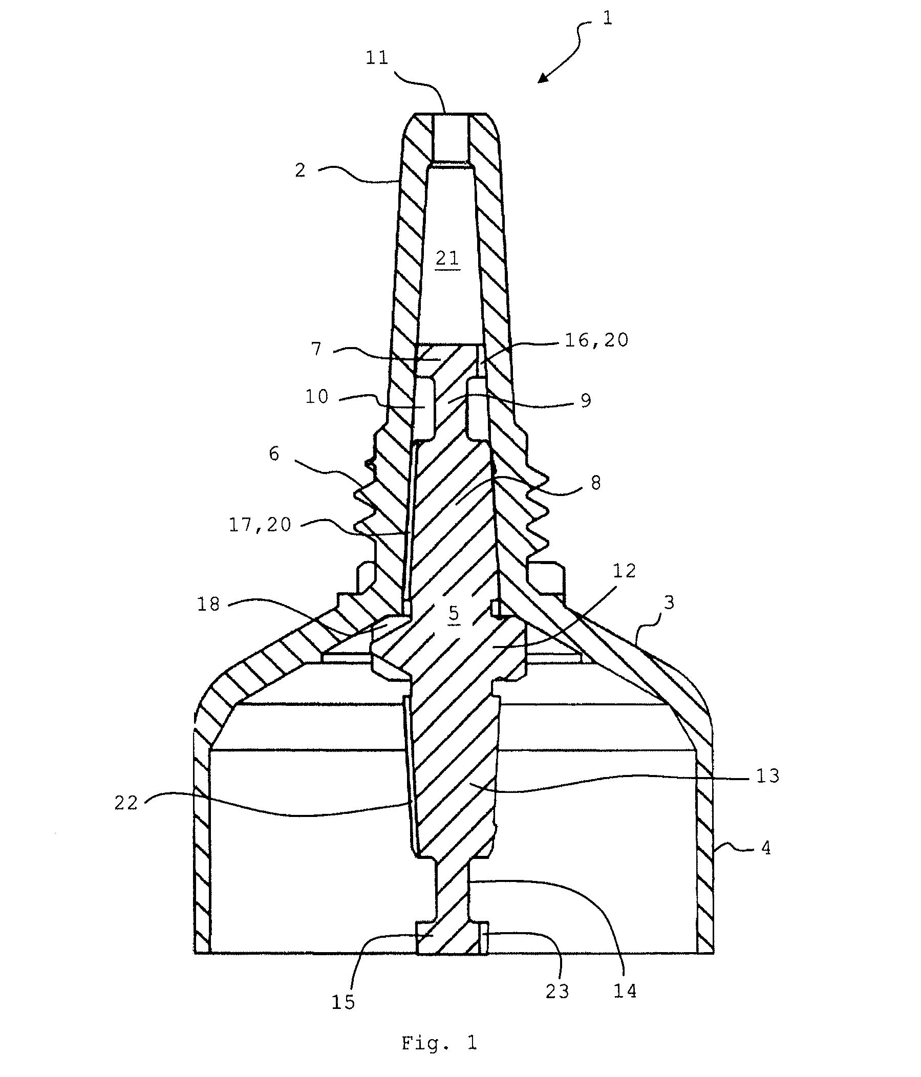
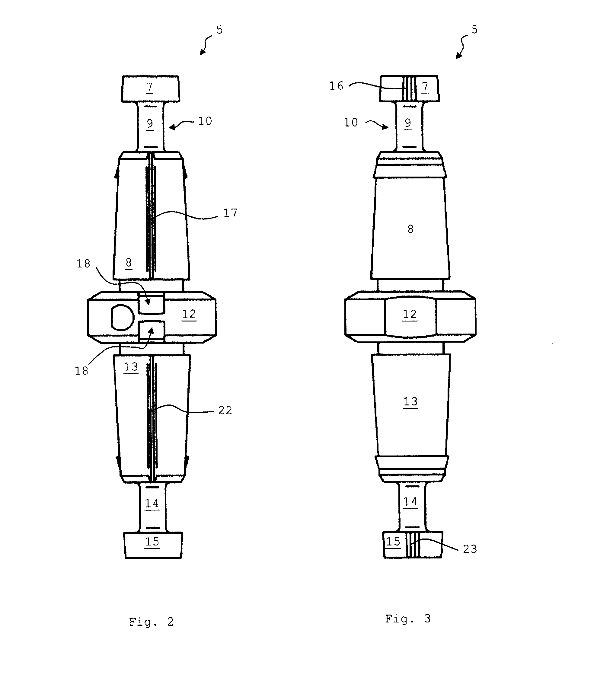
[0028]FIGS. 2 to 4 show the insert 5 of the invention in detail. The insert 5 comprises a proximal part 7 and a distal part 8 that are connected by a centrally arranged shaft 9 that is formed by an annular indentation 10 in the outer wall of the insert 5, i.e. the diameter of the shaft 9 is smaller...


PUM


Abstract

The present invention relates to an insert (5) for a tube (1) for dispensing liquid content in the form of drops, wherein the insert (5) comprises at least one notch (16; 17) at its outer wall, with the notch (16; 17) extending in the longitudinal direction, wherein the insert (5) is provided with an annular indentation (10), the annular indentation (10) dividing the insert into a proximal part (7) and a distal part (8) that are connected by a shaft (9), wherein both the proximal part (7) and the distal part (8) comprise a notch (16; 18) extending in the longitudinal direction on the respective outer wall, and wherein the outer diameter of the proximal part (7) and the outer diameter of the distal part (8) of the insert (5) are such that they match the inner diameter of a spout (2) of a tube (1), into which the insert (5) shall be placed. The invention further relates to a tube (1) with such an insert (5).

Description

CROSS REFERENCE TO RELATED APPLICATIONS[0001]This application claims the priority of PCT Application No. PCT / CH2011 / 000287, filed on Nov. 25, 2011, the disclosure of which is incorporated herein by reference in its entirety.TECHNICAL FIELD[0002]The invention relates to an insert for a tube for dispensing liquid content in the form of drops and to a tube with such an insert. Typical application areas are among others in pharmaceutics and cosmetics. The insert and the tube are especially suitable for dispensing viscose liquids.BACKGROUND[0003]With conventional tubes it is often not possible to dispense liquids in the form of drops, even if the liquids are principally able to form drops. Instead the liquid is often dispensed in the form of a jet or spurt, which makes precise dosing of the liquid difficult. With some conventional tubes drop-dispensing might be possible, if a user only applies very light pressure to the tube body, which, however, can impair ease of application and user-f...

Claims


Application Information

Patent Timeline
IPC IPC(8): B65D47/18A61F9/00
CPCB65D47/18A61F9/0008B65D35/14B65D35/40
Inventor GEIGER, ANDREASKUBESCH, CHRISTIANMATHYS, JAN
Owner HOFFMANN NEOPAC
Why Eureka
Try Eureka