Tubular Component

Active Publication Date: 2011-06-09
VIEGA TECH GMBH & CO KG
View PDF12 Cites 6 Cited by
  • Summary
  • Abstract
  • Description
  • Claims
  • Application Information

AI Technical Summary

Benefits of technology

[0018]By the substantially ring-shaped outer contour of the holding elements a crimping degree with a pipe as even as possible is achieved. The even crimping degree can preferably be improved in that the holding element is designed without flattenings, clearances and/or elevations. In this manner, the crimped connection is not weakened due to clearances and the pipe is not subjected to loads through elevations, respectively.
[0019]In a further preferred embodiment of the tubular component according to the invention the outer contours of the holding elements are designed substantially similarly except for an

Problems solved by technology

Since pipe connectors as well as pipes are subject to certain size tolerances, such premature sealing can especially occur with a pipe connector that happens to be too large and a pipe that happens to be too small.
An undiscovered,

Method used


Image

  • Tubular Component
  • Tubular Component
  • Tubular Component

Examples


Example

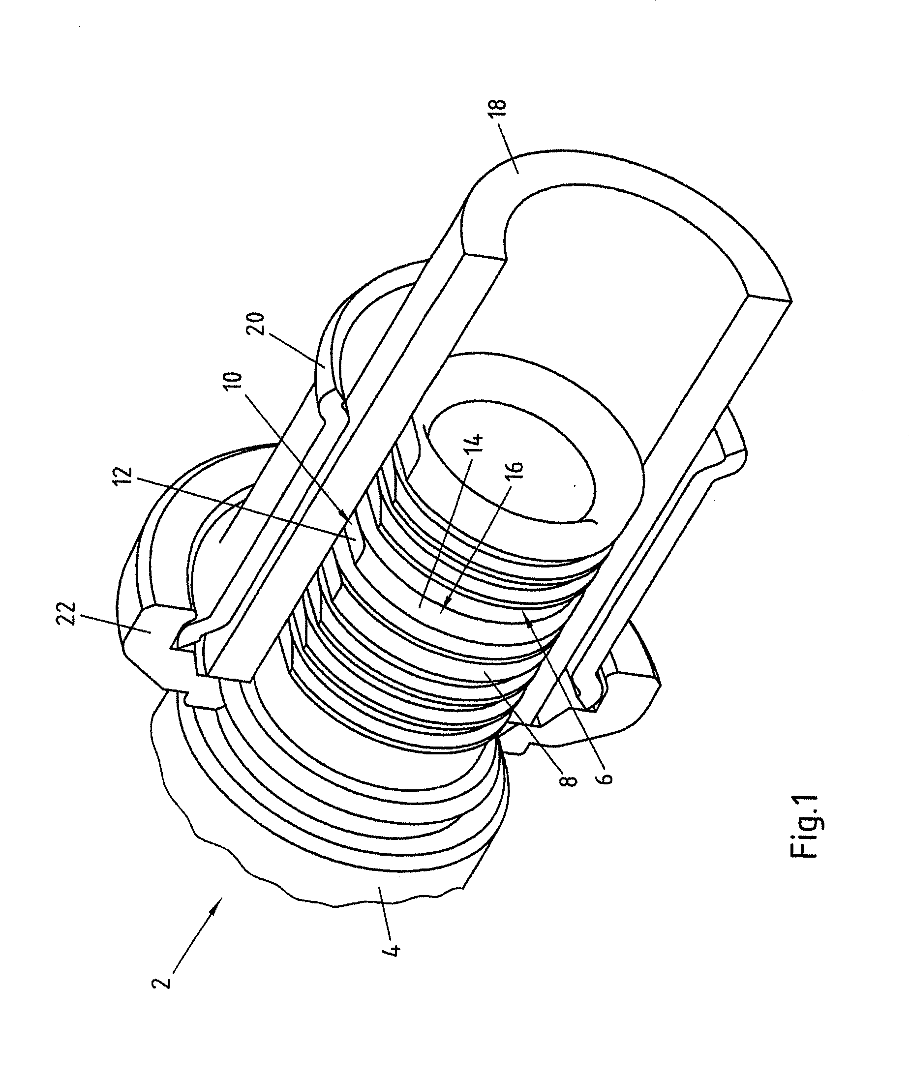
[0032]FIG. 1 shows a tubular component from the prior art in perspective part-sectional view. The tubular component 2 comprises a flange region 4 and an end section 6 with ring-shaped holding elements 8. The holding elements 6 each comprise flattenings 12 in a first azimuthal contour region 10, so that the outer contour 14 in the first contour region 10 is lowered relative to a second contour region 16. The flattening preferably amounts to between 0.1 and 0.9 mm, especially between 0.1 and 0.3 mm. The flattening can especially also comprise a curvature. To produce a connection, a pipe 18 and a crimping sleeve 20 were pushed over the end section 6 of the tubular component 2. The crimping sleeve 20 is axially fixed with a ring 22 relative to the tubular component 2. The arrangement shown in FIG. 1 is in the uncrimped state. While the outer contour 14 of the holding elements 8 in the second contour region 16 substantially contacts the inner surface of the pipe 18, the outer contour 14 ...


PUM


Abstract

A tubular component with an end section has a profile, wherein the profile comprises a plurality of holding elements axially offset in longitudinal direction of the end section. The holding elements comprise at least one first azimuthal contour region and at least one second azimuthal contour region, wherein the outer contour of a holding element in the first contour region at least in sections is lowered or raised relative to the second contour region and wherein the first contour regions of at least two holding elements are offset relative to each other in azimuthal direction.

Description

CROSS-REFERENCE TO RELATED APPLICATIONS[0001]This application is a National Phase Application which claims the benefit of and priority to German patent application no. DE 10 2009 056 975.8-24, filed on Dec. 7, 2009. The disclosures of the above applications are incorporated herein by reference in their entirety.FIELD OF THE INVENTION[0002]The invention relates to a tubular component with an end section comprising a profile, wherein the profile comprises a plurality of holding elements axially offset in longitudinal direction of the end section, wherein the holding elements comprise at least one first azimuthal contour region and at least one second azimuthal contour region and wherein the outer contour of a holding element in the first contour region at least in sections is lowered or raised relative to the second contour region.BACKGROUND[0003]In the prior art, tubular components are preferably employed as pipe connectors for joining pipes by crimping. There, a pipe is pushed over ...

Claims


Application Information

Patent Timeline
IPC IPC(8): F16L9/00
CPCF16L33/2078F16L13/148
Inventor STEINHANSES, NADINEMULLER, CHRISTIANMEISSNER, KAI-MICHAEL
Owner VIEGA TECH GMBH & CO KG
Why Eureka
Try Eureka