

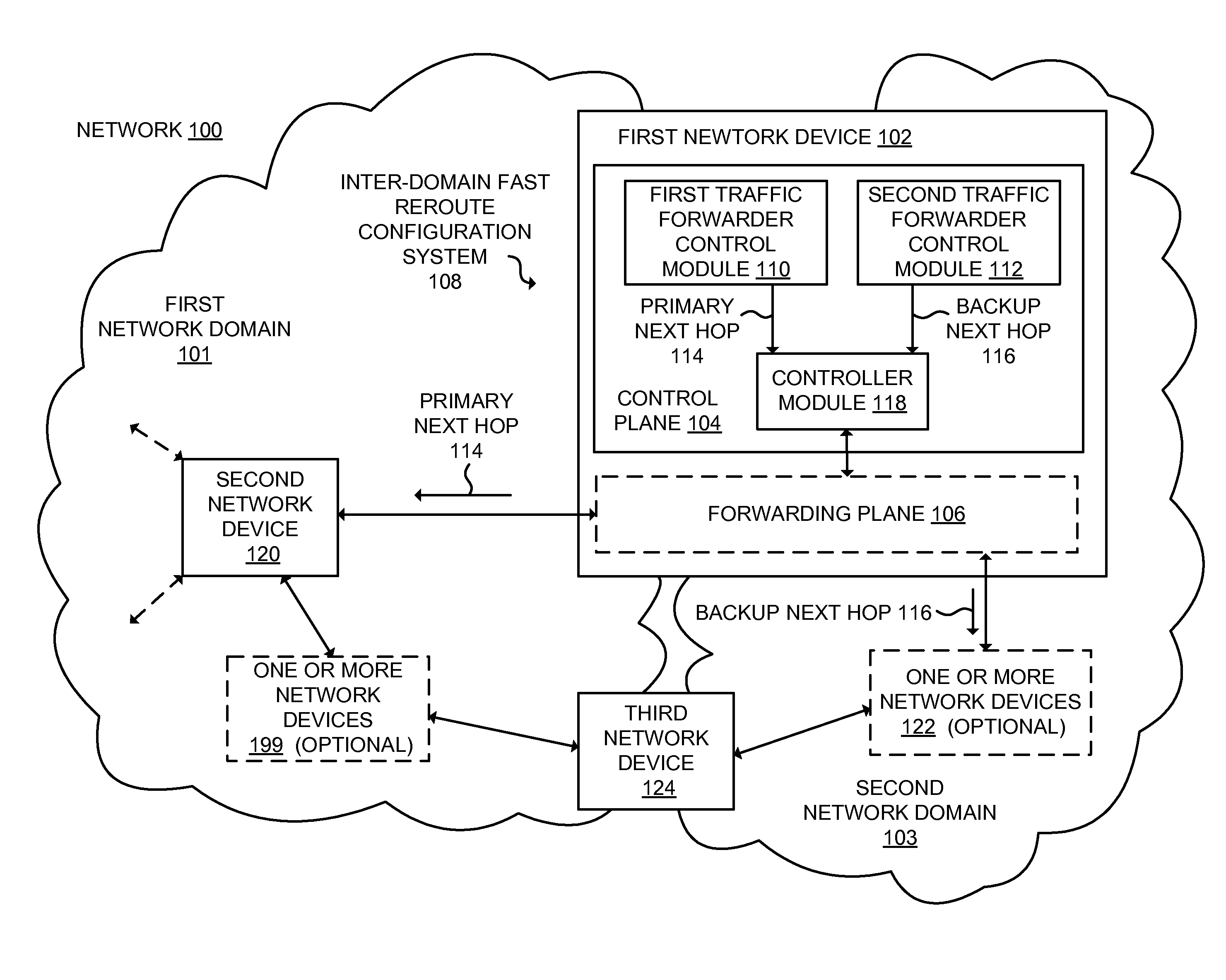
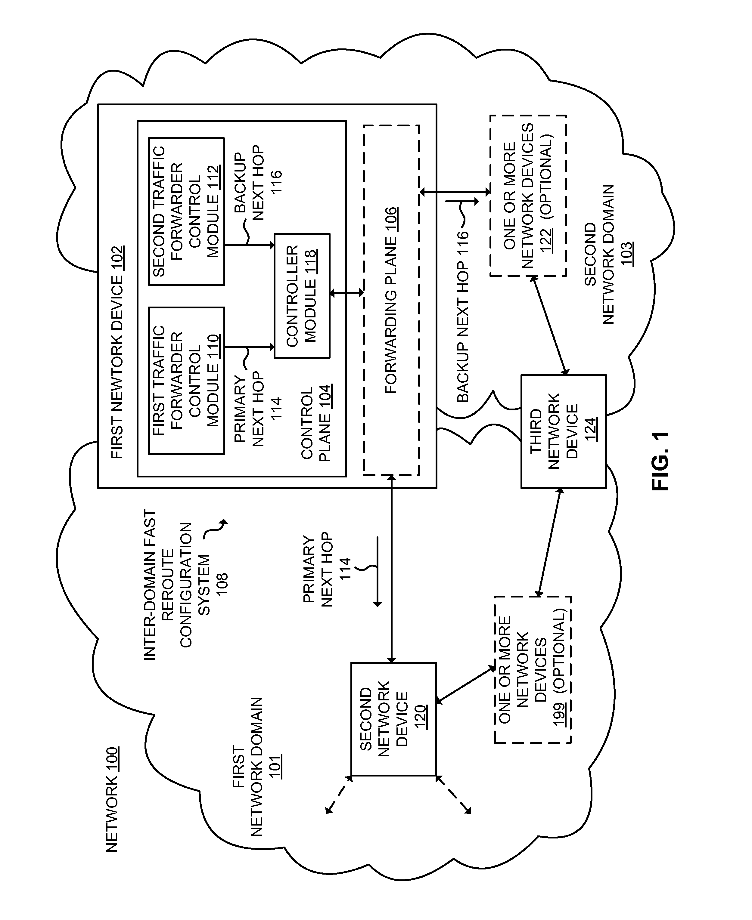
Inter-domain fast reroute methods and network devices
a network device and inter-domain technology, applied in the field of network work, can solve problems such as data loss, network failures that occur in internet protocol (ip) networks, and routing protocols typically used in such ip networks generally have relatively long convergence times
- Summary
- Abstract
- Description
- Claims
- Application Information
AI Technical Summary
Benefits of technology
Problems solved by technology
Method used
Image

Examples
first embodiment
[0067]FIG. 6 is a network 600 in which embodiments may be implemented. Some network devices provide support for implementing Virtual Private Networks (VPNs). These VPNs may be Layer 2 VPNs and / or Layer 3 VPNs. For example, network devices at the point where a provider's network and a customer's network are coupled are respectively referred to as a Provider Edge network device (PE) and a Customer Edge network device (CE). In a Layer 2 VPN, forwarding typically is performed on the CE(s) on either end of the VPN and traffic is sent across the network (e.g., through one or more PEs coupled by other network devices). Layer 2 circuits are configured between the CEs and PEs (e.g., an Ethernet port, an ATM permanent virtual circuit (PVC), a Frame Relay PVC). In a Layer 3 VPN, routing typically is performed by the PEs. By way of example, an edge network device that supports multiple contexts may be deployed as a PE, and a VPN context may be configured with a VPN protocol.
[0068]Referring agai...
second embodiment
[0071]FIG. 7 is a network 700 in which embodiments may be implemented. The network includes a first network domain 701 and a second network domain 703. The first network domain includes a prefix 742 reachable through at least a router 720. The second network domain includes a first edge router ER-1 702-1, a second edge router ER-2 702-2, a first interior router 722-1, and a second interior router 722-2. The routers are coupled by bi-directional arrows as shown in the illustration. This is just one illustrative example of a suitable network. Other networks may include other numbers and couplings of routers. In the illustration, costs or metrics associated with routing between adjacent routers on a link are shown in brackets (e.g., [10], [20], etc.).
[0072]In some embodiments, the first network domain 701 may implement a first dynamic routing protocol, such as, for example, OSPF, whereas the second network domain 703 may implement a second, different dynamic routing protocol, such as, ...
PUM
 Abstract
Description
Claims
Application Information