Lighting fixture for visible light communication and visible-light-communication system with same

a technology of visible light and communication system, applied in the field of visible light communication lighting fixtures, can solve the problems of loss of circuit, reduced modulation width (modulation ratio), led damage, etc., and achieve the effect of stabilizing the power supply voltage of the power supply circuit, suppressing the occurrence of surge current, and reducing current stress on the light sour

Active Publication Date: 2014-11-13
PANASONIC INTELLECTUAL PROPERTY MANAGEMENT CO LTD
View PDF8 Cites 10 Cited by
  • Summary
  • Abstract
  • Description
  • Claims
  • Application Information

AI Technical Summary

Benefits of technology

[0011]In the present invention, since the impedance element (Rx) connected in parallel with the switch device (Q1) is provided, the light source (11) is not put in an unloaded condition. It is therefore possible to stabilize a power supply voltage of the power supply circuit (3). An ON signal continues to flow to the control terminal of the switch device (Q1) from the ON circuit (6), and accordingly impedance between output ends of the power supply circuit (3) does not decrease sharply when the communication circuit (4) starts an ON operation. It is therefore possible to suppress the occurrence of a surge current and to reduce a current stress onto the light source (11).

Problems solved by technology

If the voltage across the output terminals of the power supply circuit rises, an input voltage onto a control power supply of the visible-light-communication controlling substrate rises as well, which causes loss of circuit.
There is a concern that LEDs suffer damage if the aforementioned surge current generates.
However, this instance causes decrease of a modulation width (modulation ratio) by ON and OFF of a switch device for modulation, which is undesirable for a visible light communication.

Method used


Image

  • Lighting fixture for visible light communication and visible-light-communication system with same
  • Lighting fixture for visible light communication and visible-light-communication system with same
  • Lighting fixture for visible light communication and visible-light-communication system with same

Examples


Embodiment Construction

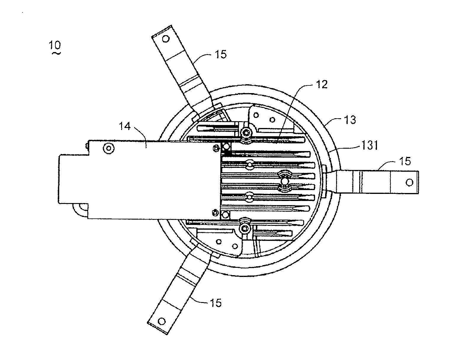
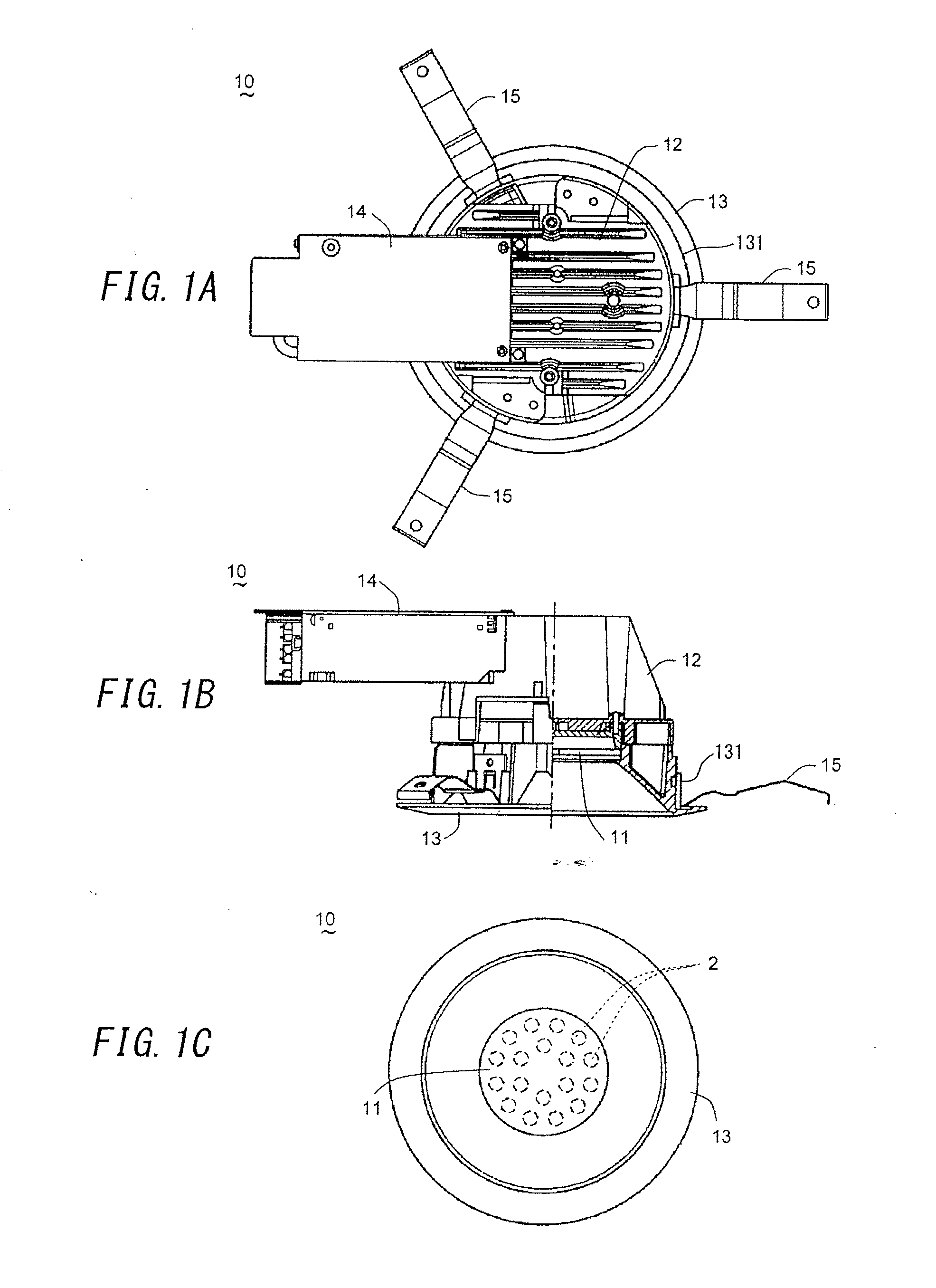
[0021]A lighting fixture for visible light communication in accordance with a first embodiment of the present invention is explained with reference to FIGS. 1A-4. FIGS. 1A and 1B show a downlight recessed in a ceiling or the like as a configuration example of the lighting fixture for visible light communication (hereinafter referred to as a “lighting fixture 10”) in the embodiment. The lighting fixture 10 includes a light source 11, a body 12, a flange frame 13, a terminal block 14 and fixing springs 15. The light source 11 includes light-emitting devices mounted on a circuit board, each of which is, for example, a light-emitting diode (an LED) 2. The body 12 houses a lighting circuit 1 configured to turn on, turn off and dim the LEDs 2 of the light source 11 (see FIG. 2 to be described). The flange frame 13 includes a cylindrical portion 131 extended upward from an inner peripheral edge thereof, and is configured to fix the body 12 housing the light source 11 or the like to a ceili...


PUM


Abstract

A lighting fixture for visible light communication is configured to modulate light intensity of a light source (11) comprising a light-emitting device (2) to superpose a communication signal on illumination light. The lighting fixture includes: a power supply circuit (3) configured to control light output of the light source (11) based on a dimming signal; a switch device (Q1) for modulating an output current from the power supply circuit (3) to the light source (11); an impedance element (Rx); a communication circuit (4); and an ON circuit (6). The communication circuit (4) is configured to supply a modulation signal to a side of the switch device (Q1) to superpose the communication signal on the illumination light. The ON circuit (6) is configured to turn on the switch device (Q1) by supply power from the power supply circuit (3) when the communication circuit (4) is inactivated.

Description

TECHNICAL FIELD[0001]The invention relates to a lighting fixture for visible light communication, configured to modulate light intensity of a light source to superpose a communication signal on illumination light of the light source, and a visible-light-communication system with the same.BACKGROUND ART[0002]Japanese Patent Application Publication No. 2011-34713 (hereinafter referred to as a “Document 1”) discloses a lighting fixture equipped with a visible-light-communication function that transmits a communication signal by using illumination light. The lighting fixture includes: a light source substrate on which a light source is mounted; a lighting circuit substrate which is electrically connected with the light source substrate and performs lighting control of the light source; and a visible-light-communication controlling substrate which superposes a communication signal on outgoing light from the light source. In the lighting fixture, the visible-light-communication controllin...

Claims


Application Information

Patent Timeline
Patent Type & Authority Applications(United States)
IPC IPC(8): H04B10/116H05B44/00
CPCH04B10/116H05B45/3725
Inventor KIDO, SHOJIROUSHIOHAMA, EIJI
Owner PANASONIC INTELLECTUAL PROPERTY MANAGEMENT CO LTD
Why Eureka
Try Eureka