Wind Park With Real Time Wind Speed Measurements

a real-time wind speed and wind farm technology, applied in the direction of instruments, process and machine control, electric generator control, etc., can solve the problems of frequent maintenance and increase the cost of the wind farm, and achieve the effect of reducing the need for and/or extent of maintenan

Inactive Publication Date: 2014-11-13
ABB POWER GRIDS SWITZERLAND AG
View PDF4 Cites 24 Cited by
  • Summary
  • Abstract
  • Description
  • Claims
  • Application Information

AI Technical Summary

Benefits of technology

[0025]By sensing equipment for sensing the at least one wind characteristic not being required for every wind turbine unit of the set of wind turbine units, the need for and / or extent of maintenance may be decreased compared to the case where sensing equipment for sensing the at least one wind characteristic is required for all wind turbine units.
[0026]In addition or alternatively, by sensing equipment for sensing the at least one wind characteristic not being required for every wind turbine unit of the set of wind turbine units, the overall cost of the system, e.g. constituting or comprising a wind farm, may be less compared to if sensing equipment for sensing the at least one wind characteristic is required for all wind turbine units in the wind farm.

Problems solved by technology

Particularly for wind farms including a relatively large number of wind turbines, the system disclosed in U.S. Pat. No. 6,975,925B1 may require frequent maintenance due to the number of instruments included in the system becoming relatively large.
For a wind farm including a relatively large number of wind turbines, the cost of the wind farm may increase significantly due to such maintenance and / or also due to the relatively large number of instruments that may be required.

Method used


Image

  • Wind Park With Real Time Wind Speed Measurements
  • Wind Park With Real Time Wind Speed Measurements
  • Wind Park With Real Time Wind Speed Measurements

Examples


Embodiment Construction

[0062]The present invention will now be described fully hereinafter with reference to the accompanying drawings, in which exemplifying embodiments of the present invention are shown. The present invention may, however, be embodied in many different forms and should not be construed as limited to the embodiments set forth herein; rather, these embodiments are provided by way of example so that this disclosure will convey the scope of the invention to those skilled in the art. Furthermore, like numbers refer to like or similar elements or components throughout. The steps of any method disclosed herein do not have to be performed in the order disclosed unless explicitly stated.

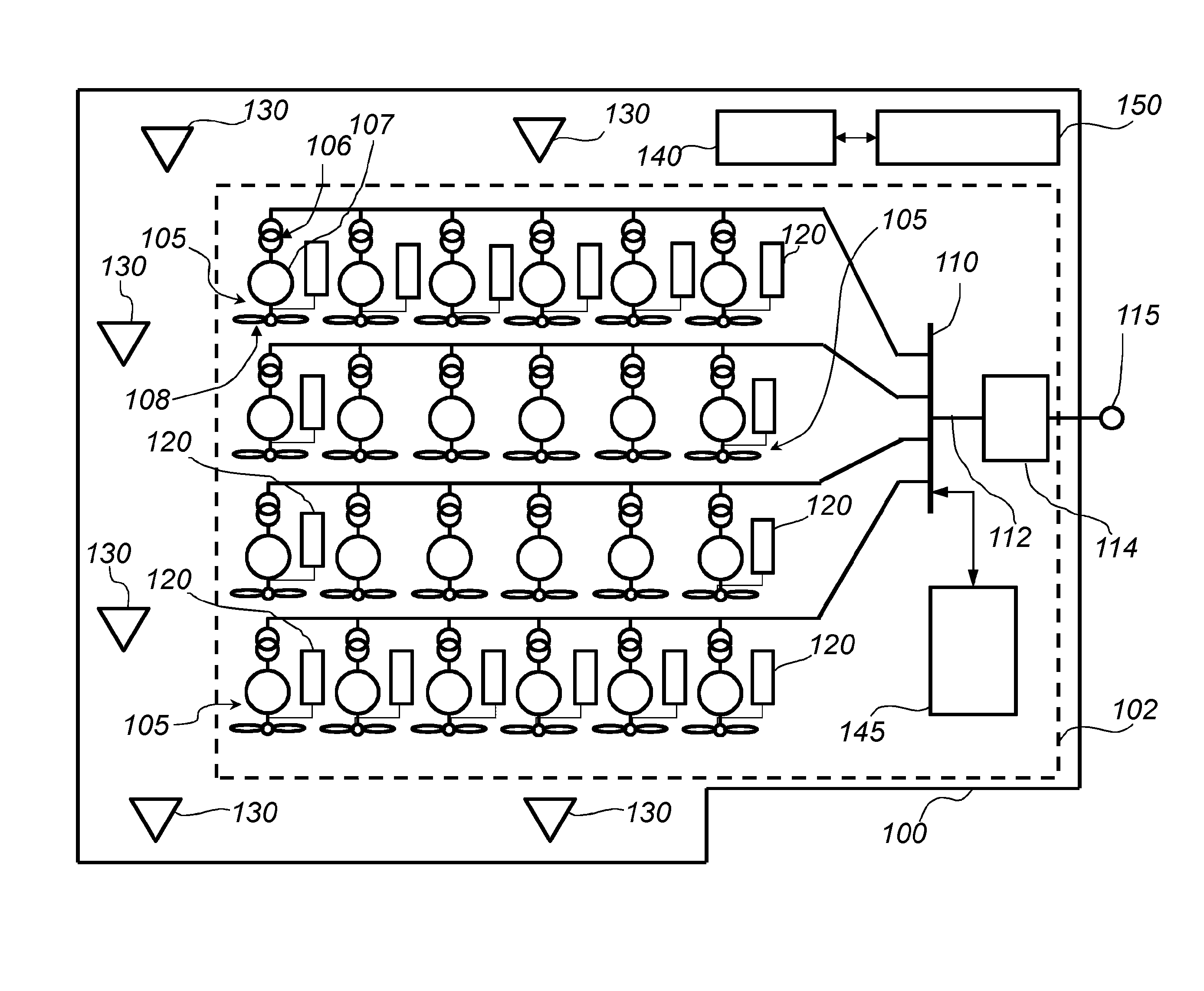
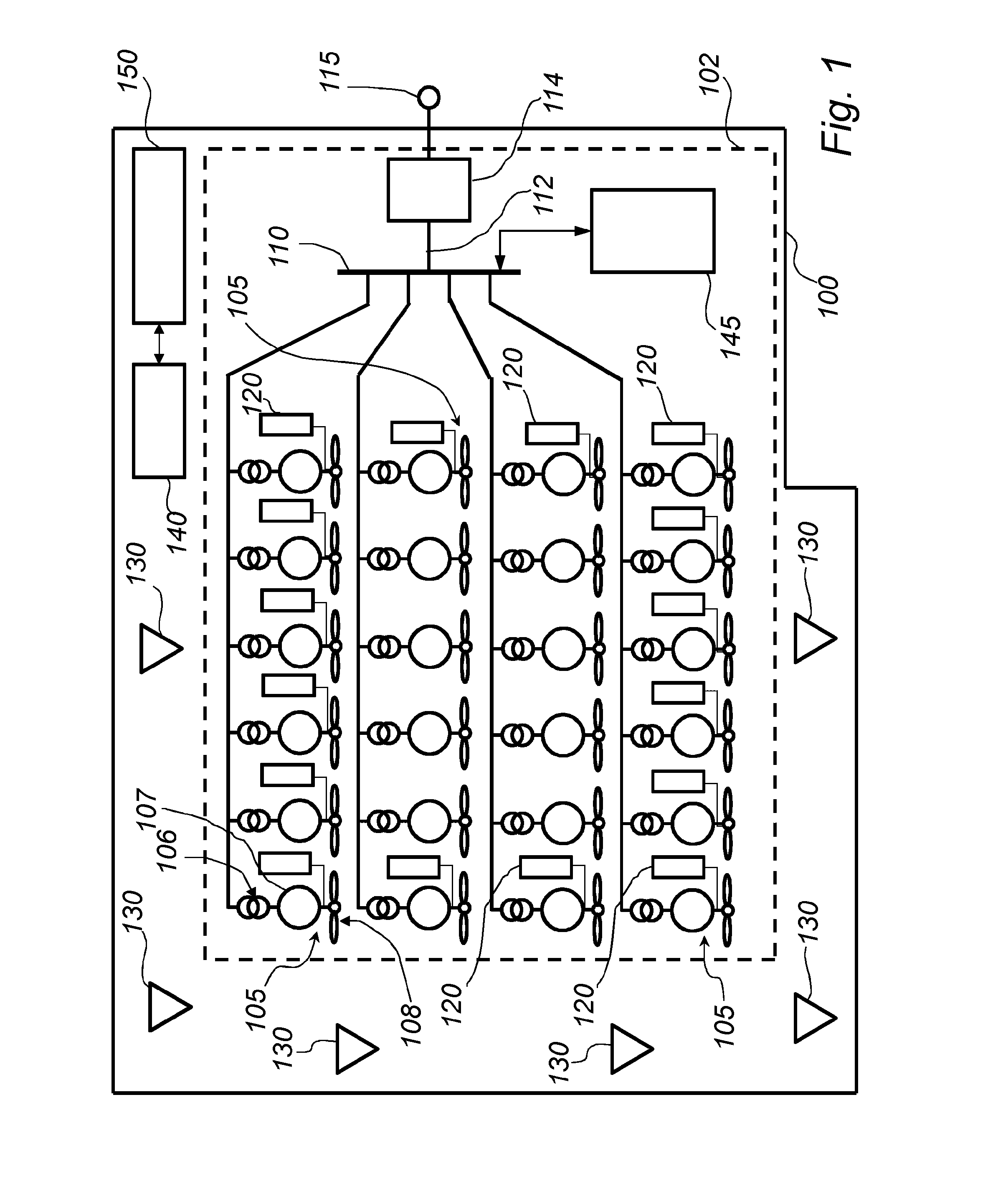
[0063]Referring now to FIG. 1, there is shown a schematic block diagram of a system 100 for producing electrical power according to an embodiment of the present invention. The system 100 comprises a wind farm or wind power plant 102.

[0064]The wind farm 102 of the system 100 comprises a set of wind turbine units. ...


PUM


Abstract

A system for producing electrical power based on wind energy is capable of predicting its power output. The system includes a set of wind turbine units, a first plurality of sensors each adapted to sense at least one wind characteristic at some of the wind turbine units, and a second plurality of sensors remotely located. At least one wind characteristic is estimated at the wind turbines not having one of the first plurality of sensors based on sensing by the first plurality of sensors and an estimate of changes in wind characteristic at wind turbine units caused by presence of other wind turbine units. The magnitude of electrical power production by the set of wind turbine units at at least one predefined point in time in the future is predicted based on the estimated wind characteristics and sensed wind characteristics.

Description

FIELD OF THE INVENTION[0001]The present invention generally relates to power generation. Specifically, the present invention relates to a system for producing electrical power, including but not limited to systems using renewable energy sources and / or any other kind of power production system for which the produced power may fluctuate, and a method of predicting a magnitude of electrical power production by a system for producing electrical power.BACKGROUND OF THE INVENTION[0002]Power plants based on fossil fuel or hydropower are in general deterministic in their power output behavior, in the sense that the output power from the power generator of the power plant may be controlled by controlling the input of the primary energy source or sources to the power generator. Power plants which are deterministic in the power output behavior are sometimes referred to as dispatchable power plants. For this type of power plant, the power output of the power generator of the power plant may be ...

Claims


Application Information

Patent Timeline
Patent Type & Authority Applications(United States)
IPC IPC(8): G06N5/04G06N99/00H02P9/00G06N20/00
CPCG06N5/04H02P9/008G06N99/005H02P2009/004F03D7/048F05B2260/821F05B2270/32F05B2270/321G01W1/10H02P2101/15F03D17/00Y02A90/10Y02E10/72G06N20/00F05B2270/204
Inventor MARINOPOULOS, ANTONISLENDENMANN, HEINZPAN, JIUPINGSRIVASTAVA, KAILASHZARGHAMI, MAHYARREZA, MUHAMAD
Owner ABB POWER GRIDS SWITZERLAND AG
Why Eureka
Try Eureka