
Compressed gas energy storage and release system

Inactive Publication Date: 2014-11-20
DE CHABRIS ANDREW MARKS
View PDF7 Cites 17 Cited by
  • Summary
  • Abstract
  • Description
  • Claims
  • Application Information

AI Technical Summary

Benefits of technology

The present invention is about a system and method for storing and releasing compressed gas energy using a geothermal heat source. The system includes a gas compressor, a container for storing the compressed gas, a pressure engine, an electrical power generating means, and a conduit for heating the compressed gas before it enters the pressure engine. The system can be located in a variety of geographic regions and can be more flexible and adaptable than previous systems. The technical effects of the invention include improved energy storage and utilization, reduced energy waste, and increased flexibility and adaptability of the system.

Problems solved by technology

One problem with the above compressed air energy storage and release systems is that as the compressed air is expanded in the pressure engine it cools rapidly on expansion.
Rapid cooling of the machinery results in 1) enbrittlement of metal, rubber or plastic components, and 2) degradation of lubricants leading, both leading to excess wear, increased maintenance costs, and unexpected failure.
The requirement for heating greatly reduces the efficiency of the compressed air storage cycle.
One problem with this approach is that it requires spending a combustible fuel, and entails generation of pollution which is harmful to the environment.
However, the Pinkerton system suffers from the same inefficiencies as the Jacoby system in that it requires spending energy to heat the cold compressed air.
Depending on what energy source is used to power the heater, the Pinkerton system may also generate of pollution which is harmful to the environment, even if it is not noxious or toxic.
A problem with Jacoby is that it requires locating a subterranean salt dome and building a generating plant located in proximity thereto.
Furthermore, Jacoby requires establishing the cavity by solution mining techniques in a salt deposit which is in thermal communication via an interconnecting spire or dome of salt with a geological “mother bed” occurring at such depths below the earth's surface as to constitute a constant high heat source, which is a difficult, and expensive procedure.
Although considered environmentally friendly, using solar power to power the cold air heaters is problematic in that the equipment necessary is expensive to acquire and install, and requires constant maintenance.
The batteries required by the solar power system are not environmentally friendly and need to be replaced at regular intervals measured in years.
Furthermore, some locations do not reliably receive sufficient sunlight to permit solar power as the sole source of power, and in most cases backup power will need to be built into the system, resulting in additional costs and inefficiencies.
Using source heat that is available on the site is also problematic in that it severely limits possible locations where the system may be built.

Method used


Image

  • Compressed gas energy storage and release system
  • Compressed gas energy storage and release system
  • Compressed gas energy storage and release system

Examples


Embodiment Construction

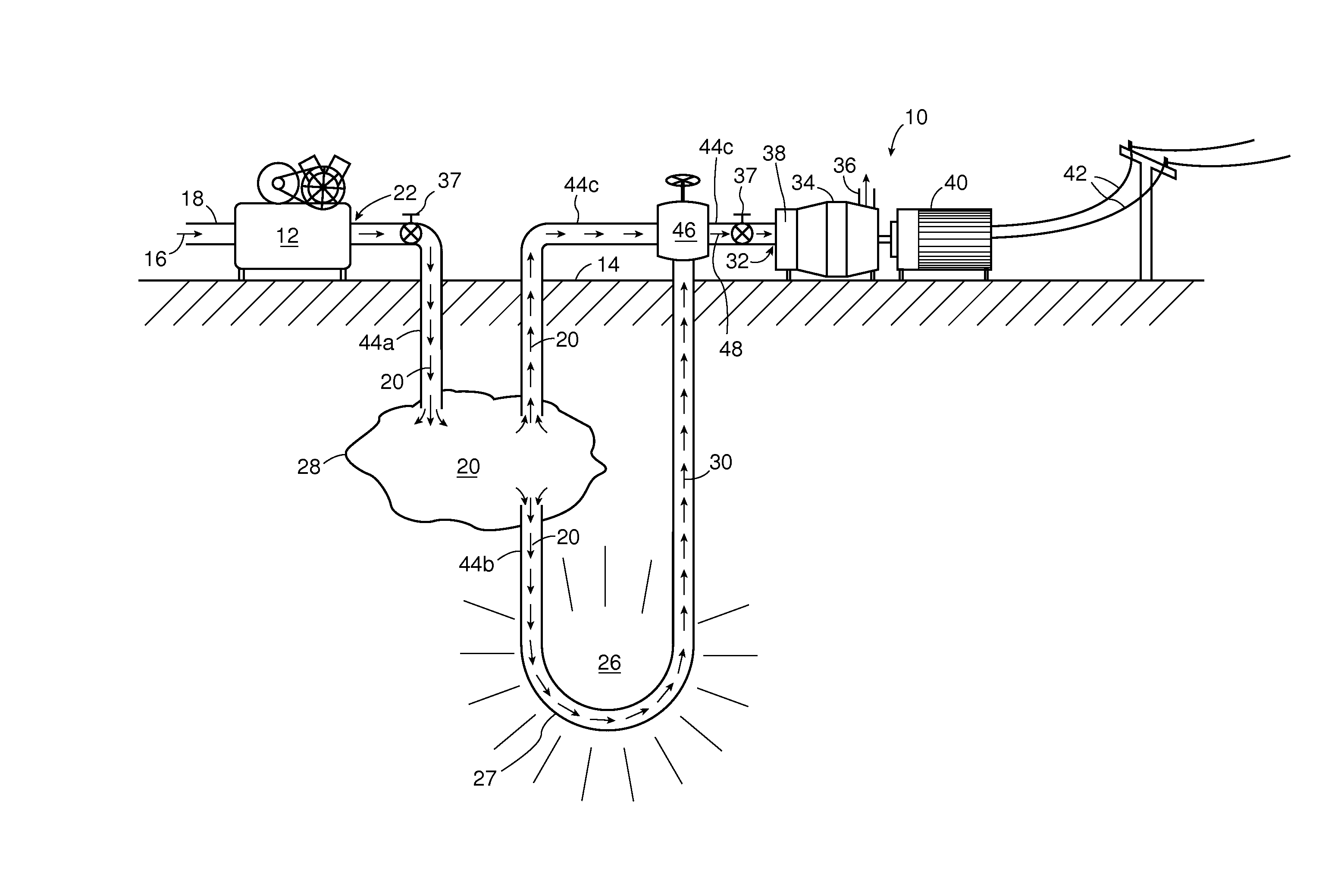
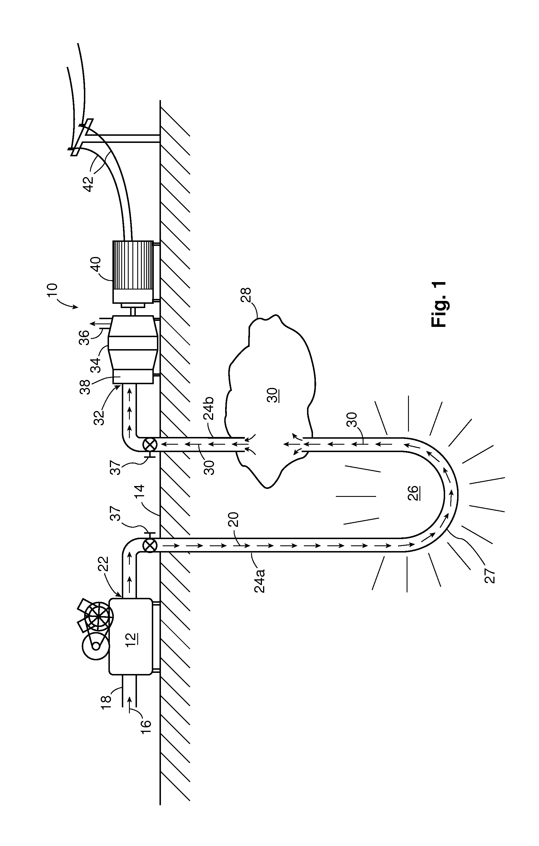
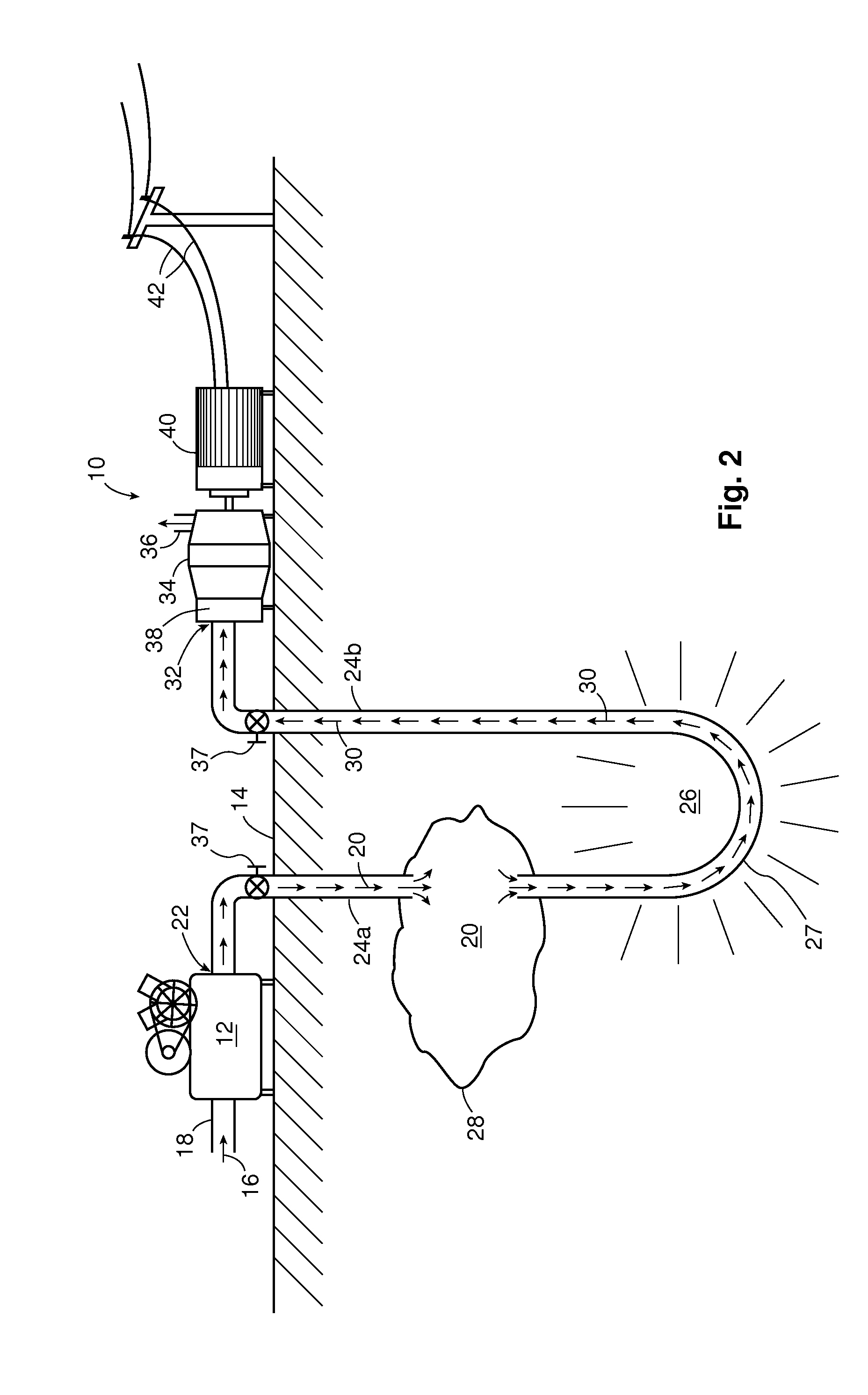
[0095]The present invention is described in more detail with reference to exemplary embodiments thereof as shown in the appended drawings. While the present invention is described below including preferred embodiments, it should be understood that the present invention is not limited thereto. Those of ordinary skill in the art having access to the teachings herein will recognize additional implementations, modifications, and embodiments which are within the scope of the present invention as disclosed and claimed herein. In the figures, like elements are given like reference numbers. For the purposes of clarity, not every component is labelled in every figure, nor is every component of each embodiment of the invention shown where illustration is not necessary to allow those of ordinary skill in the art to understand the invention.

[0096]Referring now to FIG. 1, there is shown generally at 10 a compressed gas energy storage and release (CGESR) system according to an embodiment of the p...


PUM


Abstract

A compressed gas energy storage and release (CGESR) system and method. The system has a gas compressor, a container for storing compressed gas, a pressure engine, and an underground high temperature region. Conduits connect the gas compressor, the container and the pressure engine. The compressed gas drives the pressure engine. An electrical power generating means is operatively connected to said pressure engine to generate electricity. The system further comprises a means to heat at least a portion of one of the conduits utilizing heat from the underground high temperature region to heat the compressed gas therein prior to driving the pressure engine.

Description

FIELD OF THE INVENTION[0001]The present invention relates generally to compressed gas energy storage and release (CGESR) systems. More particularly, the present invention relates to a system which provides increased efficiency and reduced system cost compared to known CGESR systems.BACKGROUND OF THE INVENTION[0002]As is known, energy may be stored in the form of compressed air in underground reservoirs comprising caverns or wells. Air compressors are used to fill such an underground reservoir, ideally during off peak times when the price of electricity is at its lowest (i.e. at night). The compressed air is then converted back into electricity and used during peak times when the price of electricity is at its highest. The conversion back to electricity is with a pressure engine such as turbine or piston engine in a known fashion.[0003]One problem with the above compressed air energy storage and release systems is that as the compressed air is expanded in the pressure engine it cools...

Claims


Application Information

Patent Timeline
IPC IPC(8): F01D15/10H02J15/00
CPCF01D15/10H02J15/006F05D2260/208F05D2260/20F05D2260/42F02C1/05F02C6/16F03G7/04Y02E60/16
Inventor MARKS DE CHABRIS, ANDREW
Owner DE CHABRIS ANDREW MARKS
Learn More