Assembled undular brake disc

Active Publication Date: 2014-11-20
FAIVELEY TRANSPORT WITTEN GMBH
View PDF19 Cites 15 Cited by
  • Summary
  • Abstract
  • Description
  • Claims
  • Application Information

AI Technical Summary

Benefits of technology

[0030]Finally, the use of a positively-joined connection makes possible the use of hub diameters which are larger compared with current connections. Since in this case the braking moment is transmitted via the positive joint o

Problems solved by technology

In order to receive axially acting pad contact pressure forces for the braking operation, the shown fan insert however is unsuitable and axial forces which

Method used


Image

  • Assembled undular brake disc
  • Assembled undular brake disc
  • Assembled undular brake disc

Examples


Embodiment Construction

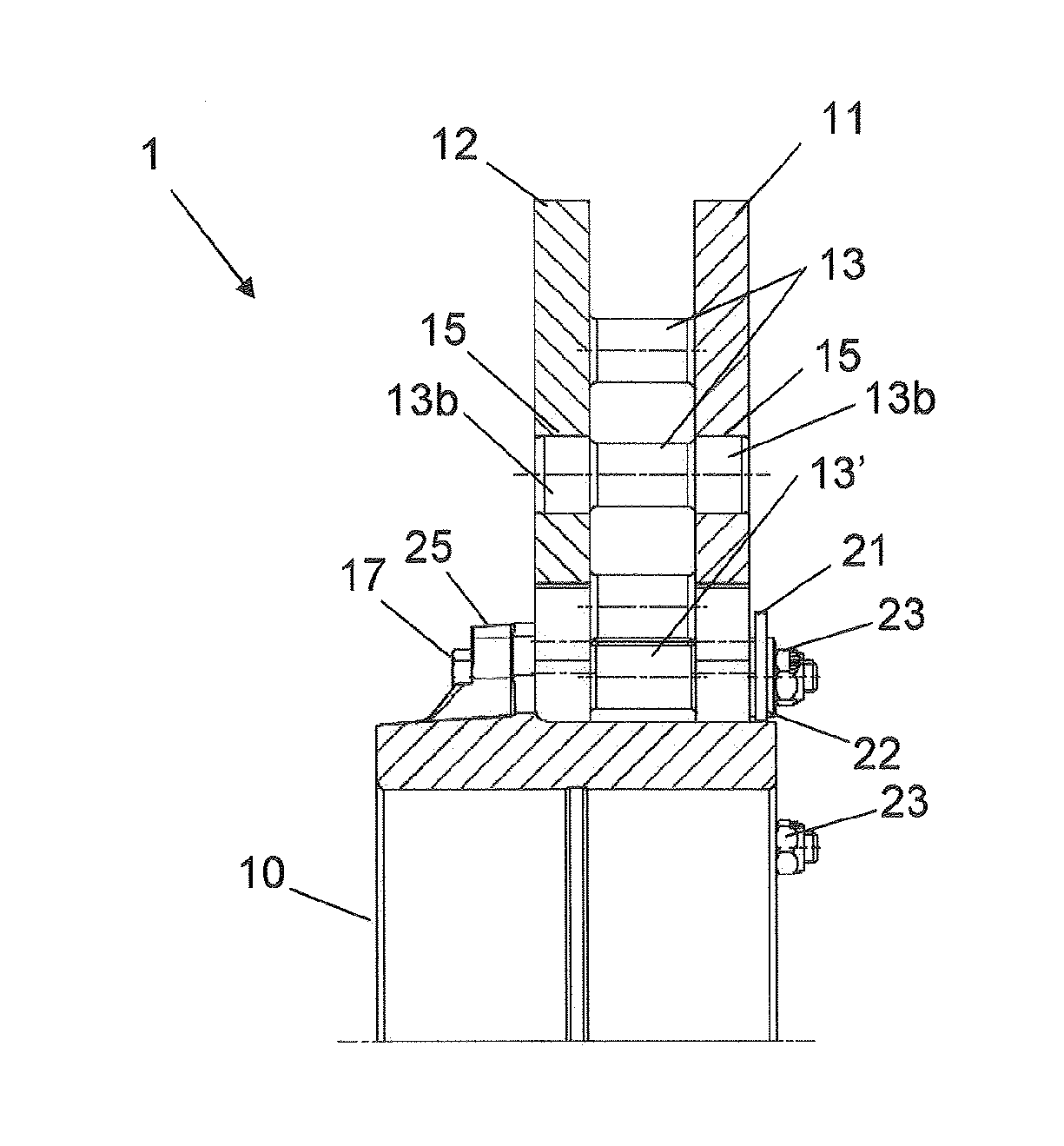
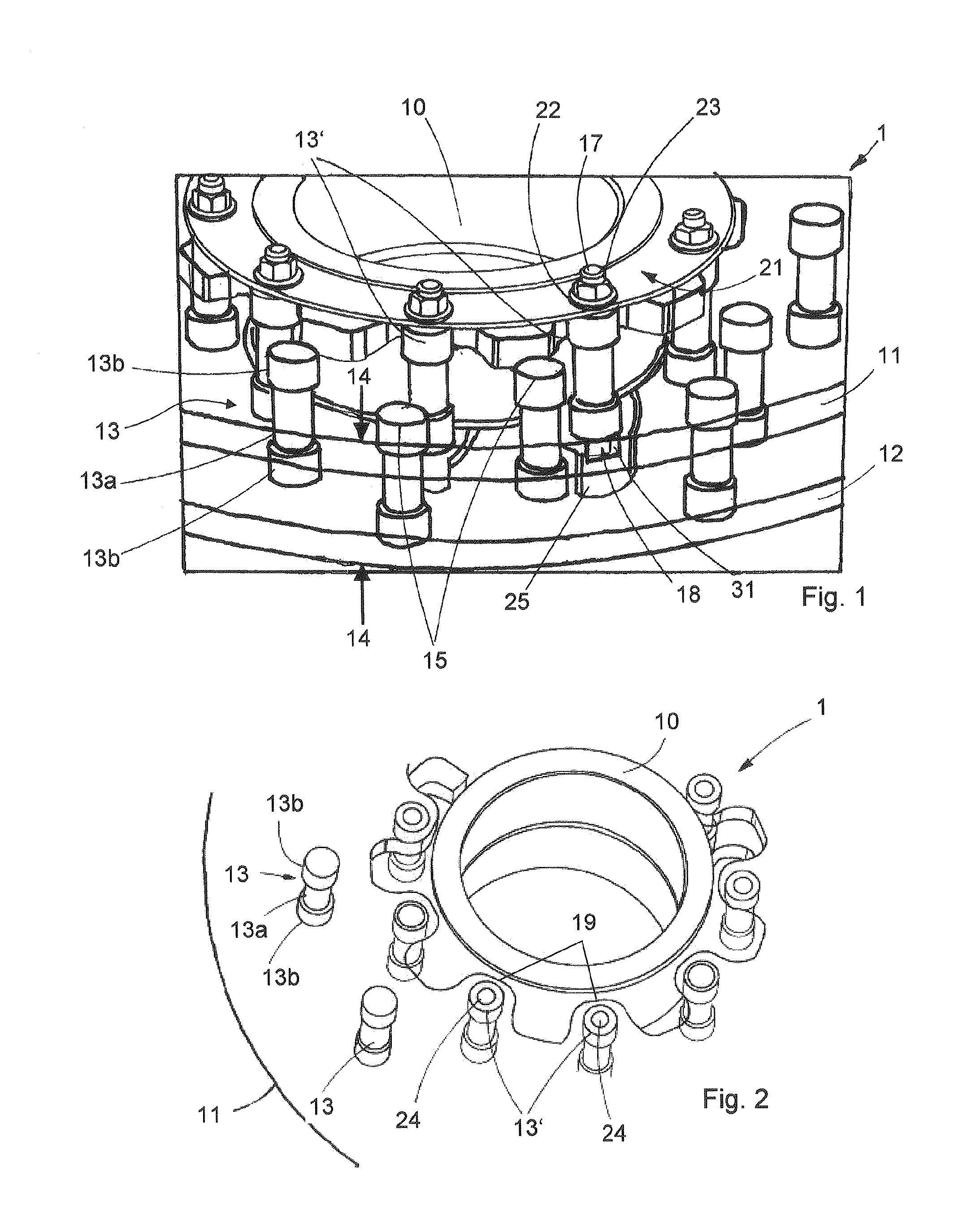
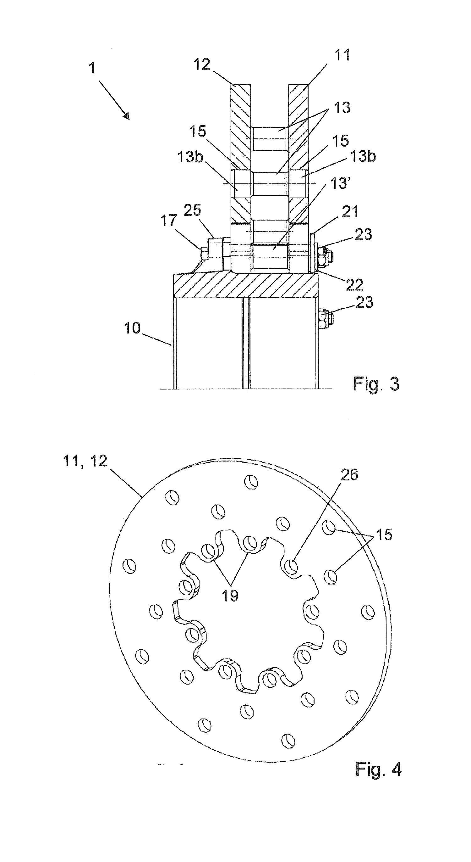
[0047]FIG. 1 shows a detail of an exemplary embodiment of a shaft brake disc 1 according to the invention with a hub 10, on which a first friction ring 11 and a second friction ring 12 arranged spaced from and parallel to the first friction ring 11 is arranged and which jointly form a friction ring pair. The shaft brake disc 1 can be employed in a brake system of a rail vehicle, and the friction rings 11 and 12 serve as friction partners for brake pads, which on the outside can be pressed onto the friction rings 11 and 12 with a brake calliper. Between the friction rings 11 and 12 multiple supporting bolts 13 are arranged, which serve for absorbing the axially acting pad contact pressure forces 14 and prevent the deformation of the friction surfaces through static and dynamic screening. The friction rings 11 and 12 are produced from steel material and are cut out of a plate material through laser beam cutting or through water jet cutting.

[0048]The supporting bolts 13 have a middle p...


PUM


Abstract

The invention relates to an assembled undular brake disc having a hub on which two friction rings which are produced from a steel material are arranged parallel to and spaced apart from one another. The assembled undular brake disc can withstand high mechanical loads and permits good internal ventilation. Supporting bolts for absorbing an axially acting pad contact pressure force are arranged between the friction rings.

Description

FIELD OF INVENTION[0001]The present invention relates to a built shaft brake disc having a hub, on which two friction rings are arranged parallel to and spaced from one another.BACKGROUND OF THE INVENTION[0002]Built shaft brake discs are employed in particular for rail vehicles, and through the built shape of the shaft brake discs these can be assembled from multiple individual components.[0003]A built shaft brake disc is to mean a shaft brake disc which is put together of at least two components. Here, a built shaft brake disc is to describe in particular a brake disc that has two friction rings which are not formed in one piece and structure-uniformly with one another, for example as is known in a casting method, but which are individually provided and preferably assembled into a friction ring pair by further elements. As a further individual part, the hub in this case can be joined to the friction ring pair in the assembly.[0004]Known are for example shaft brake discs having a hu...

Claims


Application Information

Patent Timeline
IPC IPC(8): F16D65/12
CPCF16D2065/1388F16D65/123F16D65/125F16D65/128F16D2065/1316F16D2065/1328F16D2065/1356F16D2065/1392F16D2200/0021
Inventor WURTH, SEBASTIANMEHLAN, ANDREAS
Owner FAIVELEY TRANSPORT WITTEN GMBH
Why Eureka
Try Eureka