Method for bonding wafers and structure of bonding part

Active Publication Date: 2014-11-20
ORMON CORP
View PDF2 Cites 13 Cited by
  • Summary
  • Abstract
  • Description
  • Claims
  • Application Information

AI Technical Summary

Benefits of technology

[0010]According to one or more embodiments of the present invention, a method for bonding wafers and a structure of a bonding part is capable of preventing the bonding part from deteriorating due to AuSn.

Problems solved by technology

However, when the molten AuSn solder comes in contact with the adhesive layer and the AuSn diffuses into the adhesive layer when the bonding parts are bonded, adhesive force between the adhesive layer and the wafer deteriorates, and reliability reduces in the bonding part.
However, the bonding part is formed of

Method used


Image

  • Method for bonding wafers and structure of bonding part
  • Method for bonding wafers and structure of bonding part
  • Method for bonding wafers and structure of bonding part

Examples


Embodiment Construction

[0036]Hereinafter, embodiments of the present invention will be described with reference to the accompanying drawings. However, the present invention is not limited to the following embodiments, and can be variously designed without departing from the scope of the present invention. In embodiments of the invention, numerous specific details are set forth in order to provide a more thorough understanding of the invention. However, it will be apparent to one of ordinary skill in the art that the invention may be practiced without these specific details. In other instances, well-known features have not been described in detail to avoid obscuring the invention.

Structure of Bonding Part and Bonding Method

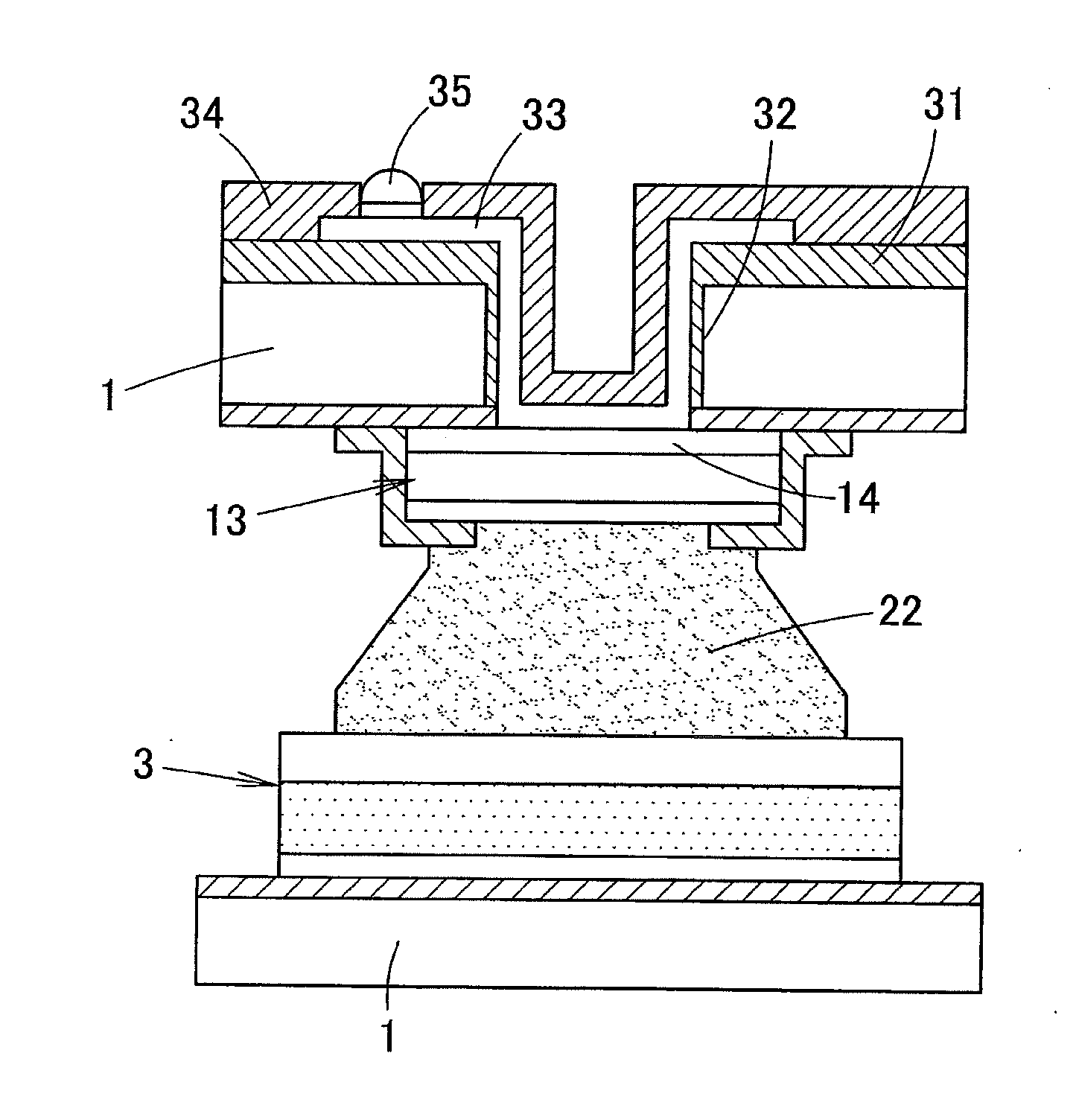
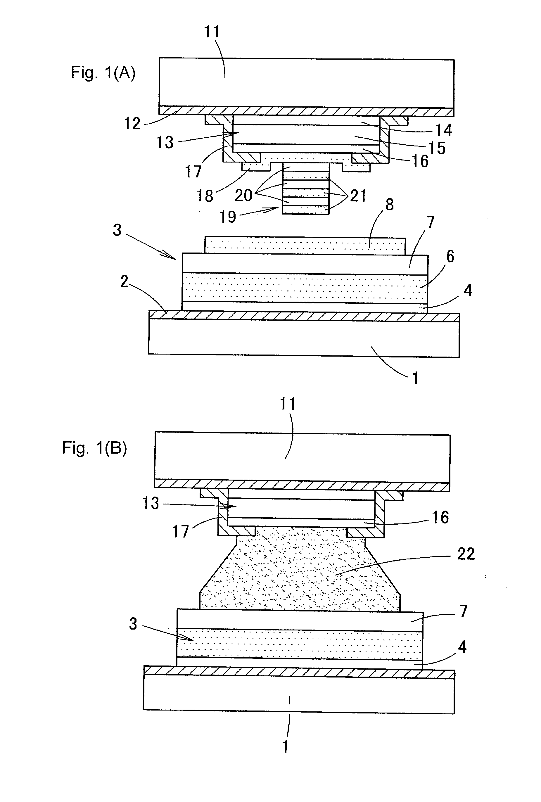
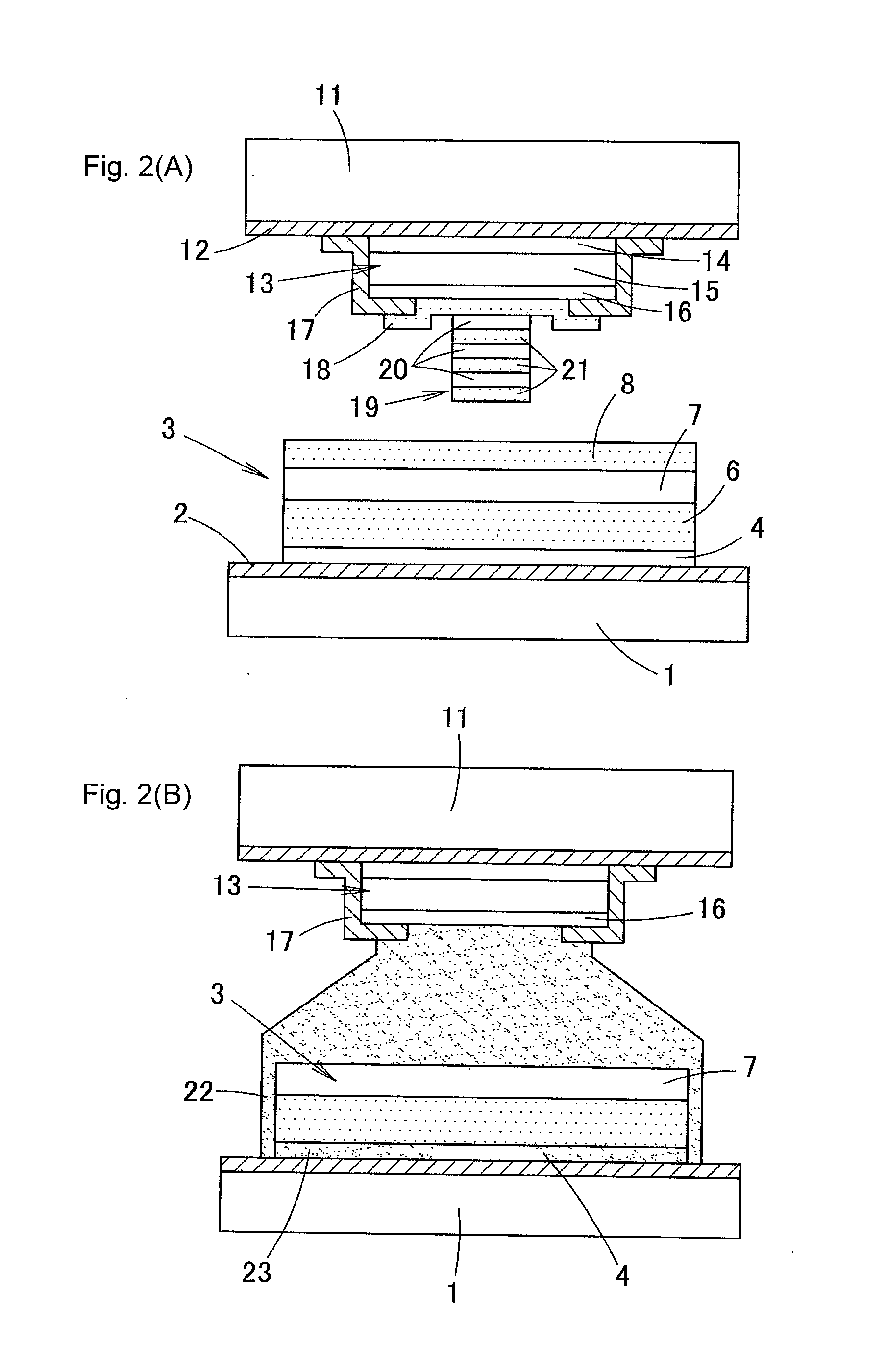
[0037]FIGS. 1A and 1B are schematic cross-sectional views to describe a method for bonding wafers according to one or more embodiments of the present invention. FIG. 1A shows a structure before a first wafer and a second wafer are bonded, and FIG. 1B shows a structure after the wafers ha...


PUM


Abstract

A method for bonding wafers includes forming a first bonding part on a surface of a first wafer by stacking a diffusion preventing layer formed of a material having low wettability with AuSn above the first wafer and forming a bonding layer on a surface of the diffusion preventing layer such that the bonding layer stays back of an edge of the diffusion preventing layer, forming a second bonding part on a surface of a second wafer, and bonding the first bonding part and the second bonding part by eutectic bonding with an AuSn solder under a condition that the first wafer and the second wafer are opposed to each other.

Description

BACKGROUND[0001]1. Technical Field[0002]The present invention relates to a method for bonding wafers and a structure of a bonding part, and more particularly, to a method for bonding two wafers by AuSn eutectic bonding and a structure of its bonding part.[0003]2. Related Art[0004]When bonding parts of two wafers are bonded, AuSn eutectic bonding is used in some cases. The AuSn eutectic bonding means a bonding method using an eutectic reaction of a metal and AuSn and is used in fields of advanced MEMS packaging and three-dimensional stacking technique. According to the AuSn eutectic bonding, the AuSn is melted like a solder, and it has an advantage that bonding can be easily performed even when a surface of the bonding part is rough like a plated layer.[0005]Thus, when the bonding parts of the wafers are bonded by the AuSn eutectic bonding, as for one wafer, an adhesive layer formed of Cr is provided in some cases as a layer (lowermost layer) which is in contact with the wafer (refer...

Claims


Application Information

Patent Timeline
IPC IPC(8): H01L23/00
CPCH01L24/05H01L24/03H01L24/29H01L2924/01322H01L2224/05083H01L2224/29171H01L2224/05144H01L24/83H01L23/02H01L23/10H01L21/50B81C1/00269B81C2203/019H01L2224/1308H01L2224/32502H01L2224/16502H01L2224/13178H01L24/13H01L24/16H01L24/32H01L24/81H01L2224/02372H01L2224/05124H01L2224/05147H01L2224/05155H01L2224/05166H01L2224/05184H01L2224/05548H01L2224/06182H01L2224/13007H01L2224/13022H01L2224/13111H01L2224/13144H01L2224/13164H01L2224/13169H01L2224/13173H01L2224/13176H01L2224/14181H01L2224/1601H01L2224/16058H01L2224/16506H01L2224/2908H01L2224/3201H01L2224/32058H01L2224/32506H01L2224/81193H01L2224/81805H01L2224/83193H01L2224/83805H01L2224/94H01L2924/1461H01L2224/0401H01L25/50H01L2924/00012H01L2924/0105H01L2224/81H01L2224/83H01L2924/00014H01L2924/00H01L25/065H01L25/07H01L25/18
Inventor FUJIWARA, TAKESHIOKUNO, TOSHIAKIINOUE, KATSUYUKIYAMAMOTO, JUNYAHINUMA, KENICHIASHIHARA, YOSHIKIMIYAJI, TAKAAKI
Owner ORMON CORP
Why Eureka
Try Eureka