Virtual image display apparatus

a virtual image and display device technology, applied in the field of virtual image display devices and projectors, can solve the problems of eye fatigue in burden on the eyes of observers, and large eyelid burden of observers, so as to reduce the eye burden of observers during use and suppress the stress of observers

Active Publication Date: 2014-11-20
SEIKO EPSON CORP
View PDF19 Cites 21 Cited by
  • Summary
  • Abstract
  • Description
  • Claims
  • Application Information

AI Technical Summary

Benefits of technology

[0008]An advantage of some aspects of the invention is to provide a virtual image display apparatus that can reduce a burden on the eyes of an observer during use and suppress stress of the observer even in long-time use.
[0009]An aspect of the invention is directed to a virtual image display apparatus including: a video device; a light guide member arranged in front of the eye of an observer and configured to direct light emitted from the video device to the eye of the observer and cause the observer to visually recognize an image; a frame configured to arrange the light guide member in a predetermined position in front of the eye and support the light guide member on the basis of a support position reference plane decided assuming at least a standard position of the eye; and an adjusting section configured to adjust an emission state of the light from the light guide member with respect to the eye of the observer. The light guide member emits light, which the light guide member should cause the observer to visually recognize, from a direction angled with respect to the support position reference plane and causes the observer to visually recognize the image from an overlooking direction for causing the eye of the observer to overlook the downward side. The adjusting section changes an angle in the overlooking direction with respect to the position of the eye of the observer by adjusting an emission state of the light from the light guide member. The support position reference plane is a plane including at least a standard position of the human eyes as an index used as a reference in designing a support position of the virtual image display apparatus assuming standard sizes, a standard positional relation, and the like concerning the human eyes, nose, and ears. By setting the support position reference plane as the reference, it is possible to cause an observer having standard facial features to visually recognize an image with a visual line from an overlooking direction at an ideal intended depression angel (e.g., a depression angle of 10° with respect to the front direction).
[0010]In the visual image display apparatus, according to design based on the support position reference plane decided assuming the standard positions of the human eyes and the like, the observer can observe a video in a state in which the visual line of the observer is caused to overlook the downward side. Therefore, it is possible to reduce a burden on the eyes of the observer during use and suppress stress of the observer even in long-time use. In particular, in the virtual image display apparatus, even when the positions of the eyes, the nose, and the ears of the observer deviate from the standard positions and the observer cannot observe a video in a targeted overlooking direction in a worn state in standard setting, it is possible to change the angle in the overlooking direction and cause the observer to observe the video with a suitable visual line by adjusting an emission state of light from the light guide member according to individual differences of the observer using the adjusting section.
[0019]In still yet further another aspect of the invention, the adjusting section adjusts an angle in the overlooking direction with respect to a front direction of the eye of the observer to be within a range of an angle larger than 0° and equal to or smaller than 15°. Consequently, it is possible to moderately change the angle in the overlooking direction without causing the observer to feel a sense of discomfort.

Problems solved by technology

As a result, a large burden is imposed on the eyelids and the like of the observer.
The burden on the eyes during the observation also occurs in observation of a video with a virtual image display apparatus such as an HMD.
If the observer looks straight forward and the burden is imposed on the eyes for a long time, the observer feels stress due to fatigue in the eyes.
However, in the observation on the virtual image display apparatus such as the HMD, the observer observes the video while wearing the apparatus, unlike the observation on the television or the like, it is difficult to change the posture of the observer according to the position of the video.
Even if the virtual image display apparatus is designed such that the visual line of the observer is directed to the downward side in a standard worn state, the observation of the video is not always performed as designed.

Method used


Image

  • Virtual image display apparatus
  • Virtual image display apparatus
  • Virtual image display apparatus

Examples


first embodiment

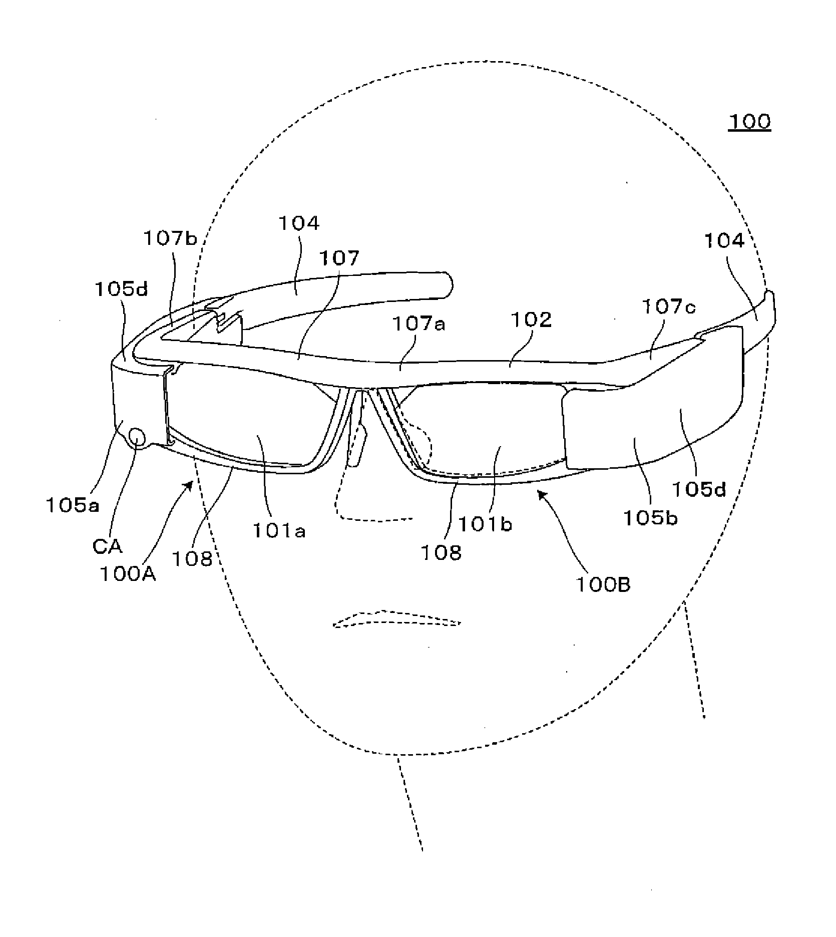
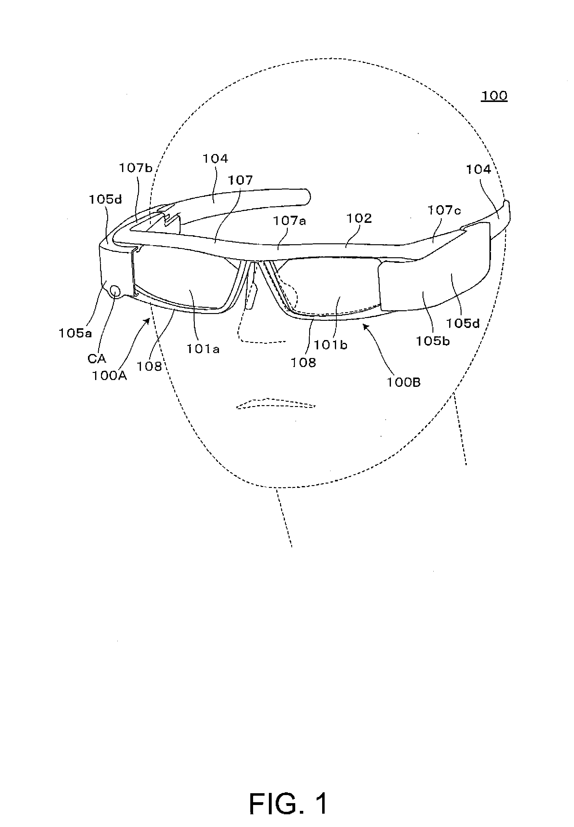
[0043]A virtual image display apparatus according to a first embodiment of the invention is explained in detail below with reference to FIG. 1 and the like.

[0044]As shown in FIG. 1, a virtual image display apparatus 100 in this embodiment is a head mounted display having an external appearance like eyeglasses. The virtual image display apparatus 100 can cause an observer or a user wearing the virtual image display apparatus 100 to visually recognize image light formed by a virtual image and can cause the observer to visually recognize or observe an external image by see-through. The virtual image display apparatus 100 includes first and second optical members 101a and 101b configured to cover the front of the observer to be seen through, a frame section 102 configured to support the optical members 101a and 101b, and first and second image forming main body sections 105a and 105b added to portions from left and right ends of the frame section 102 to temple sections (temples) 104 in ...

second embodiment

[0092]A virtual image display apparatus according to a second embodiment is explained with reference to FIG. 9A to 9C. The virtual image display apparatus in this embodiment is a modification of the virtual image display apparatus 100 in the first embodiment. The virtual image display apparatus in this embodiment is the same as the virtual image display apparatus 100 in the first embodiment except the structure of an adjusting section including a nose receiving section. Therefore, only the nose receiving section and sections around the nose receiving section are explained. The entire configuration and the like of the virtual image display apparatus are not shown in the figures and not explained.

[0093]FIG. 9A is a diagram schematically showing an example of an adjusting section including a nose receiving section 140 in the virtual image display apparatus according to this embodiment. FIGS. 9B and 9C are diagrams schematically showing attachment and detachment of a pair of left and ri...

third embodiment

[0094]A virtual image display apparatus according to a third embodiment is explained below with reference to FIGS. 10A to 10C. The virtual image display apparatus in this embodiment is a modification of the virtual image display apparatus 100 in the first embodiment and the like. The virtual image display apparatus in this embodiment is the same as the virtual image display apparatus 100 in the first embodiment except the structure of temple sections. Therefore, only the temple sections and sections around the temple sections are shown in the figures and explained. The entire configurations and the like of the virtual image display apparatus are not shown in the figures and not explained. A pair of temple sections has a symmetrical structure. Therefore, only one of the temple sections is shown in the figures and explained. The other is not shown in the figures and not explained.

[0095]FIG. 10A is a diagram showing an example of a temple section 104 in the virtual image display appara...


PUM


Abstract

An observer can observe a video in a state in which the visual line of the observer is caused to overlook the downward side. In particular, in a virtual image display apparatus, even when the positions of the eyes, the nose, and the ears of the observer deviate from standard positions and the observer cannot observe a video in a targeted overlooking direction in a worn state in standard setting, it is possible to change an angle in an overlooking direction with respect to a front direction and cause the observer to perform observation in a suitable visual line by changing, with a nose receiving section functioning as an adjusting section, the posture of the virtual image display apparatus and adjusting an emission state of video light from a light guide member according to individual differences of the observer.

Description

BACKGROUND[0001]1. Technical Field[0002]The present invention relates to a virtual image display apparatus and a projector that present a video formed by a video display apparatus to an observer and, more particularly, to a virtual image display apparatus suitable for a head mounted display mounted on the head of the observer.[0003]2. Related Art[0004]Various virtual image display apparatuses are proposed as a virtual image display apparatus such as a head mounted display (hereinafter also referred to as HMD) mounted on the head of an observer (see, for example, JP-A-2012-163640 (Patent Literature 1)).[0005]The virtual image display apparatus such as the HMD is desired to attain an increase in an angle of view without deteriorating image quality while being reduced in size and weight.[0006]When an observer views a video on a television or the like, if the observer views the video for a long time in a straight forward state, the observer observes the video in a wide-open state of the...

Claims


Application Information

Patent Timeline
Patent Type & Authority Applications(United States)
IPC IPC(8): G02B27/01
CPCG02B2027/0178G02B27/0172G02B27/0179G02B2027/0154G02B2027/0158
Inventor HIRAIDE, NORIAKI
Owner SEIKO EPSON CORP
Why Eureka
Try Eureka