Control unit, display device including control unit, and control method

a display device and control unit technology, applied in the direction of instruments, computing, electric digital data processing, etc., can solve the problem of non-uniform brightness of liquid crystals, and achieve the effect of suppressing non-uniform brightness

Inactive Publication Date: 2014-11-20
SHARP KK
View PDF1 Cites 24 Cited by
  • Summary
  • Abstract
  • Description
  • Claims
  • Application Information

AI Technical Summary

Benefits of technology

[0032]The present invention can suppress non-unifo...

Problems solved by technology

This may result in non-unifor...

Method used


Image

  • Control unit, display device including control unit, and control method
  • Control unit, display device including control unit, and control method
  • Control unit, display device including control unit, and control method

Examples


embodiment 1

Configuration Example of Liquid Crystal Display Device

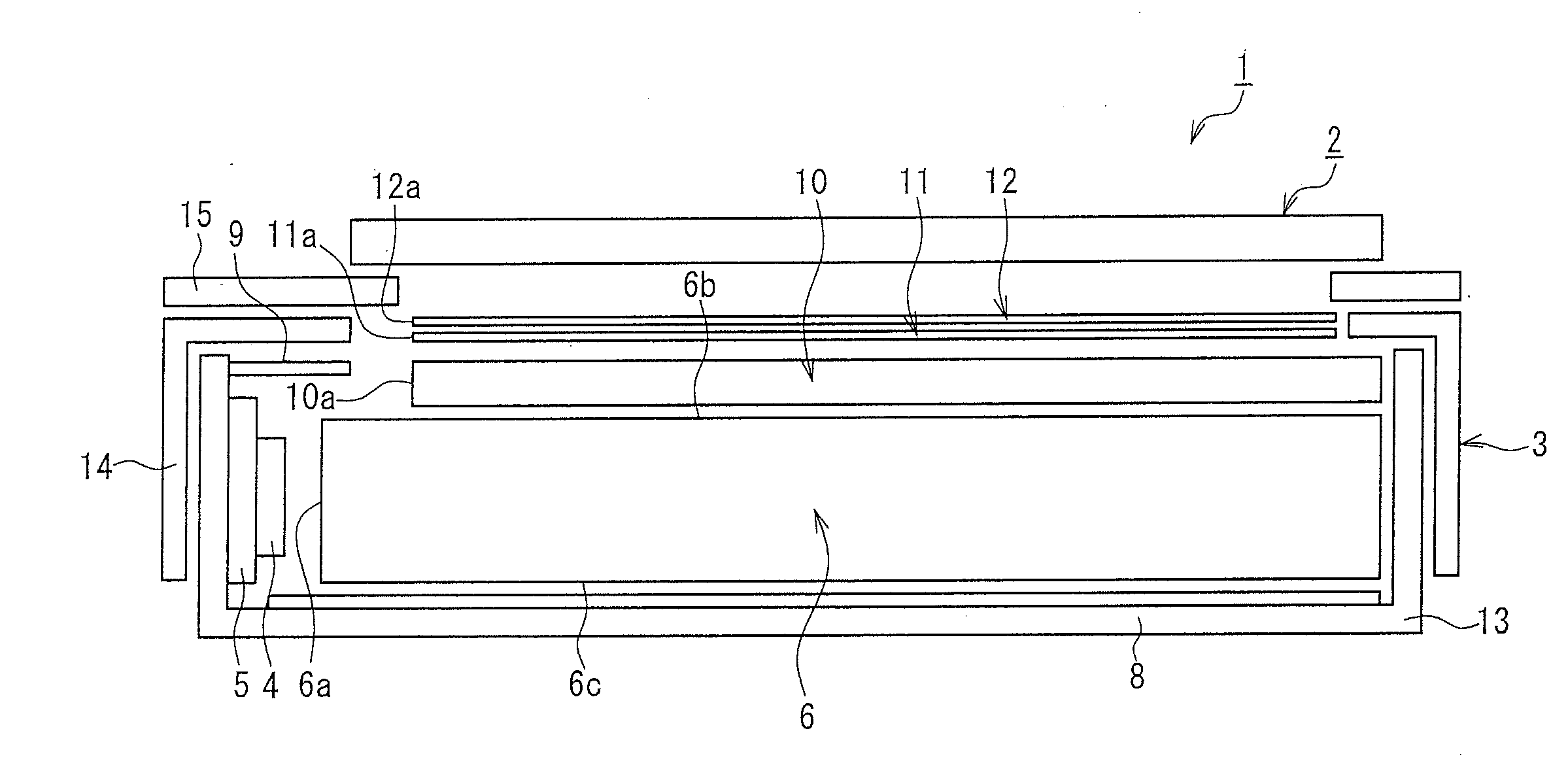
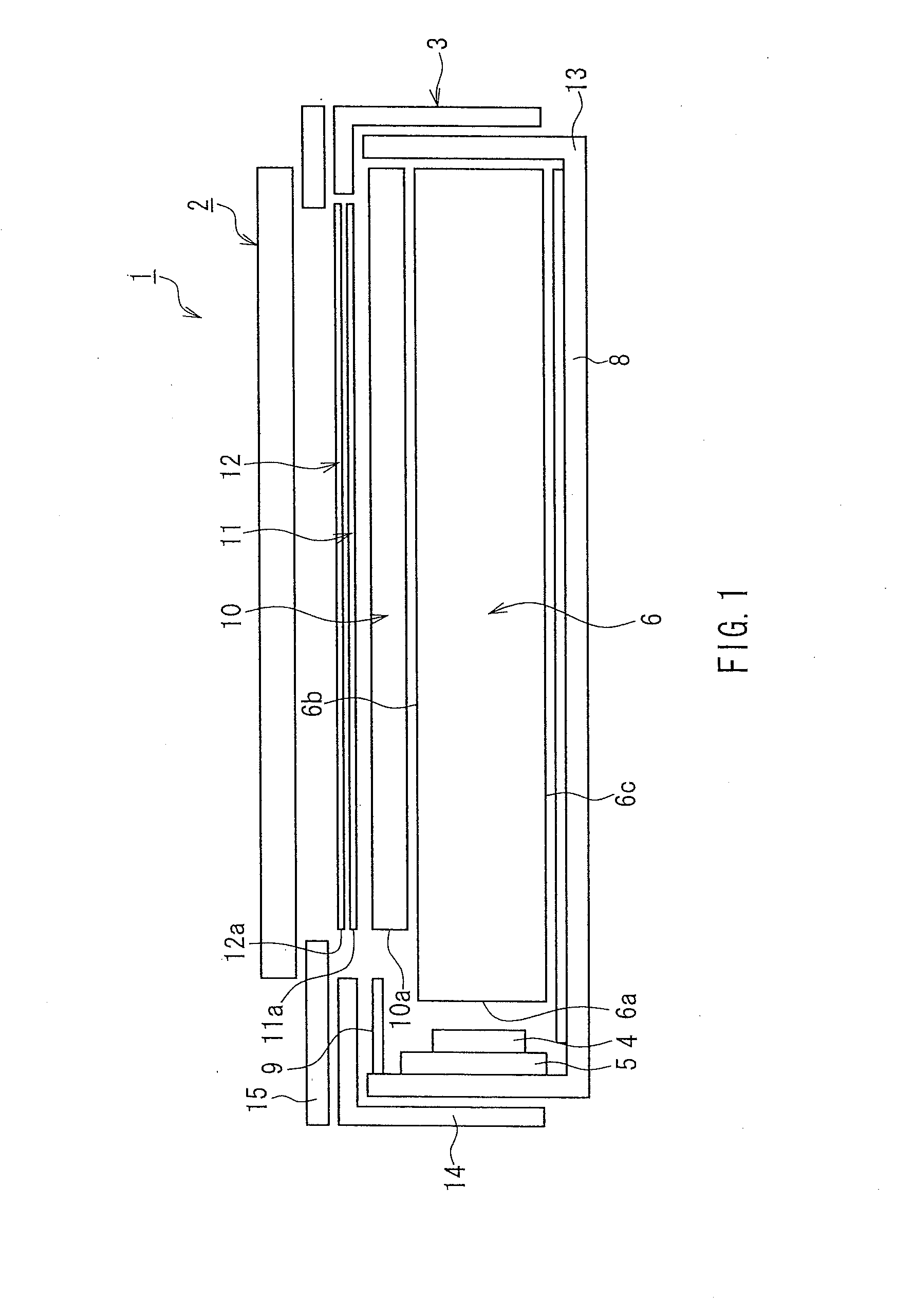
[0046]FIG. 1 is a diagram for explaining a liquid crystal display device of Embodiment 1 of the present invention. In FIG. 1, a liquid crystal display device 1 of this embodiment includes a liquid crystal panel (display portion) 2 for displaying information and a backlight device (backlight portion) 3. In the liquid crystal display device 1, the liquid crystal panel 2 uses illumination light from the backlight device 3 to display information. The liquid crystal panel 2 and the backlight device 3 are integrated into the transmission type liquid crystal display device 1.

[0047]The liquid crystal panel 2 includes a liquid crystal layer, and an active matrix substrate and a color filter substrate that are a pair of substrates sandwiching the liquid crystal layer (not shown). As will be described in detail later, pixel electrodes, thin film transistors (TFTs), or the like are formed between the active matrix substrate and the liquid cr...

second embodiment

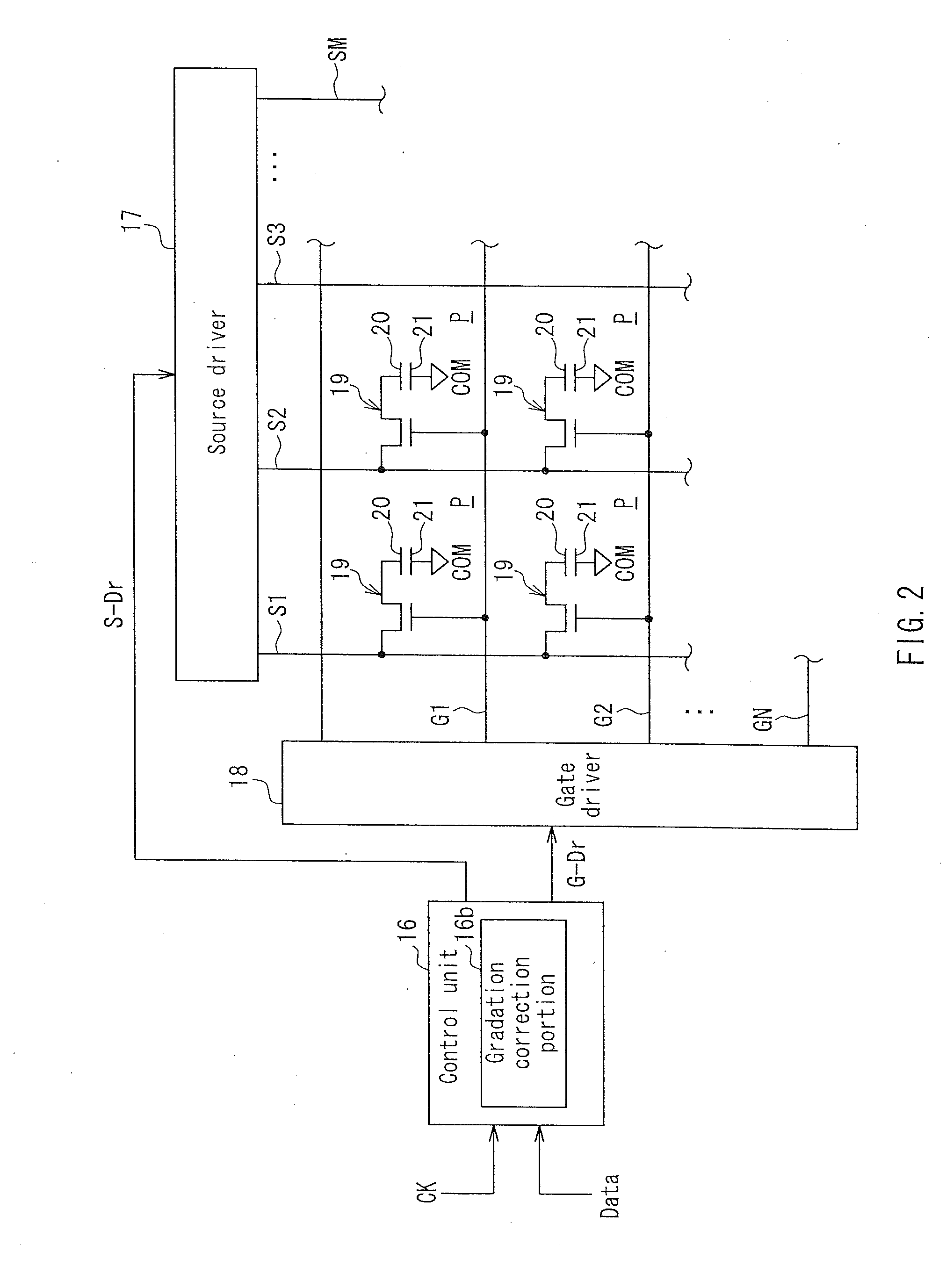
[0110]FIG. 6 is a functional block diagram showing a configuration example of a control unit of Embodiment 2. In this embodiment, the gradation correction portion 16b of the control unit 16 includes an operation portion 16c. The operation portion 16c receives the signals RGB that are generated by the chrominance demodulator 42 and the signal generator 43 and indicate the gradation of each pixel, and performs an operation to determine the correction values for the gradation values indicated by the signals RGB. In this embodiment, the display region of the liquid crystal panel 2 is divided into a plurality of regions (first display region and second display region) that differ in the drive frequency. The operation portion 16c performs a first operation to determine the correction values for the gradation values of the pixels in the first display region, and a second operation to determine the correction values for the gradation values of the pixels in the second display region. The fi...

modified examples

[0116]Next, modified examples that can be applied to both Embodiments 1 and 2 will be described.


PUM


Abstract

A control unit (16) is provided in a display device having a plurality of pixels and controls a display signal indicating gradation of the pixels. The control unit (16) includes a gradation correction portion (16b) that determines correction values for gradation values of each of the pixels indicated by the display signal in accordance with a drive frequency of the pixels.

Description

TECHNICAL FIELD[0001]The present invention relates to a technology for controlling a signal indicating the gradation of a plurality of pixels in a display device.BACKGROUND ART[0002]In recent years, flat panel display devices including, e.g., liquid crystal display devices have been widely used as display portions of electrical products such as a computer and a television.[0003]These display devices generally include a display screen in which a large number of pixels are arranged in a matrix, and images are sequentially displayed on the display screen based on an input clock signal and an image signal that is synchronized with the clock signal. The pixels arranged in a matrix in the display screen are connected to many gate lines and many source lines that are similarly arranged in rows and columns in this display screen. When a gate voltage is applied to the gate lines, a row of pixels connected to each of these gate lines are selected, and a source voltage is applied to the select...

Claims


Application Information

Patent Timeline
IPC IPC(8): G09G3/20
CPCG09G3/2003G09G2320/0276G09G2320/0242G09G3/3426G09G2320/0233G09G2320/0285G09G2320/0673
Inventor YAMAKAWA, RYO
Owner SHARP KK
Why Eureka
Try Eureka