Display device

a display device and display technology, applied in the field of display devices, can solve the problems of undesirable characteristics and inability to solve the problem of color moire, and achieve the effect of reducing moire intensity and increasing crosstalk

Inactive Publication Date: 2014-11-20
PANASONIC INTELLECTUAL PROPERTY CORP OF AMERICA
View PDF2 Cites 24 Cited by
  • Summary
  • Abstract
  • Description
  • Claims
  • Application Information

AI Technical Summary

Benefits of technology

[0023]An object of the present invention is to provide technologies for reducing moire intensity without a significant increase in crosstalk.

Problems solved by technology

The aforementioned characteristics are undesirable, for example, when the display device 900 is a portable device such as a tablet.
Even when the slant barrier is used, the problem of color moire may not be solved.

Method used


Image

  • Display device
  • Display device
  • Display device

Examples


first embodiment

Display Device

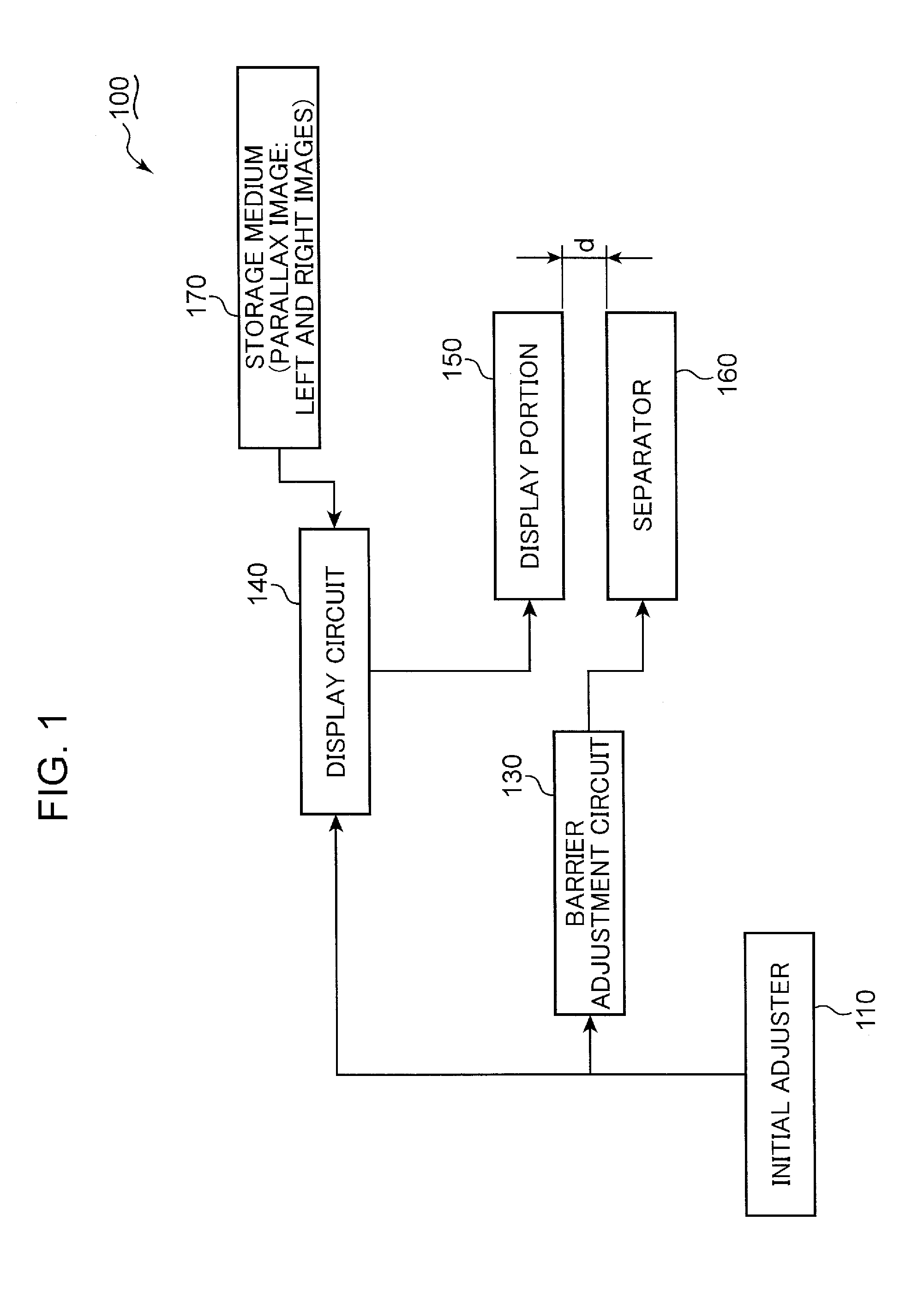
[0083]FIG. 1 is a schematic block diagram of the display device 100 according to the first embodiment. The display device 100 is described with reference to FIGS. 1, 47A and 47B.

[0084]The display device 100 includes an initial adjuster 110, a barrier adjustment circuit 130, a display circuit 140, a display portion 150, a separator 160 and a storage medium 170. The initial adjuster 110 performs initial adjustments to the barrier adjustment circuit 130 and the display circuit 140. The storage medium 170 stores image data about parallax images, which are obtained by synthesizing a left image to be viewed by a left eye and a right image to be viewed by a right eye. The image data is transferred from the storage medium 170 to the display circuit 140. The display circuit 140 processes the image data to generate drive signals. The drive signals are transferred from the display circuit 140 to the display portion 150. The display portion 150 displays parallax images (2D) in res...

second embodiment

Display Device

[0189]FIG. 14 is a schematic block diagram of the display device 100A according to the second embodiment. The display device 100A is described with reference to FIG. 14. It should be noted that the same reference numerals are assigned to elements which are common with the first embodiment. The description in the first embodiment is applied to the elements to which the same reference numerals are assigned.

[0190]Like the first embodiment, the display device 100A includes the initial adjuster 110, the barrier adjustment circuit 130, the display circuit 140 and the storage medium 170. The display device 100A further includes a display portion 150A and a separator 160A. The display portion 150A displays images under a display pattern which is different from the first embodiment. The separator 160A is formed to be suitable for the display pattern created by the display portion 150A.

(Display Pattern)

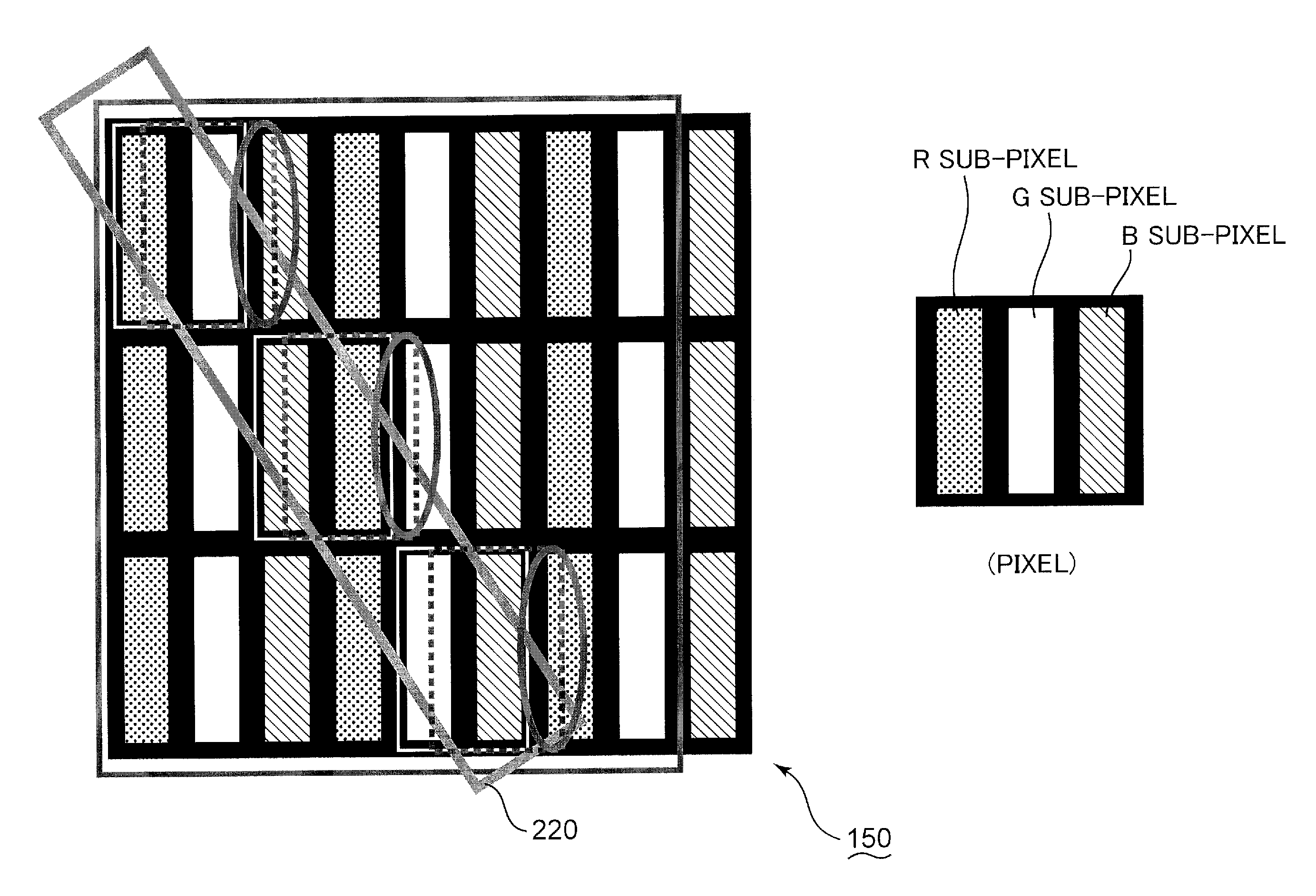
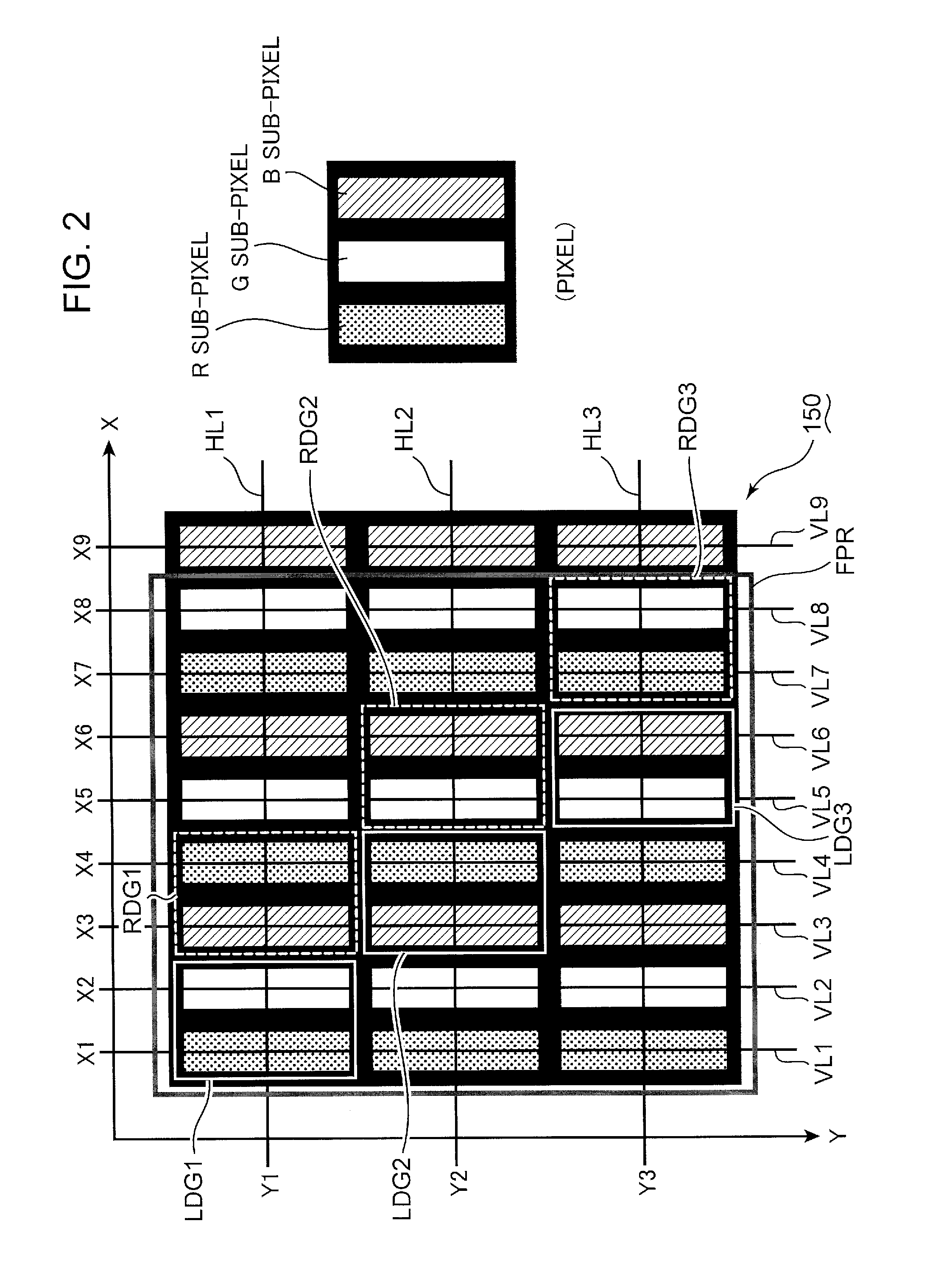
[0191]FIG. 15 is a schematic view of the display portion 150A. The display po...

third embodiment

Display Device

[0253]FIG. 25 is a schematic block diagram of the display device 100B according to the third embodiment. The display device 100B is described with reference to FIG. 25. It should be noted that the same reference numerals are assigned to elements common with the first embodiment. The explanation of the first embodiment may be applied to the elements to which the same reference numerals are assigned.

[0254]Like the first embodiment, the display device 100B includes the initial adjuster 110, the barrier adjustment circuit 130, the display circuit 140 and the storage medium 170. The display device 100B further includes a display portion 510, a separator 520, a camera 530, a detector 540, a switching portion 550, and a controller 560.

[0255]The camera 530 captures a region where there is a viewer viewing images displayed by the display portion 510 and generates image data. The image data is output from the camera 530 to the detector 540. The detector 540 uses the image data t...


PUM


Abstract

The present application discloses a display device including a display portion for displaying a composite image of left and right images to be viewed by left and right eyes by using display elements arranged in a matrix. The display portion defines first and second element groups for displaying the left and right images, respectively. The first element groups include first and second height group situated at first and second vertical positions, which is different from each other. The second element groups include first and second adjacent groups horizontally adjacent to the first and second height group, respectively. The first and second adjacent groups include first and second adjacent elements adjacent to the first and second height groups, respectively. The first adjacent element emits different light in a luminescent color from the second adjacent element.

Description

TECHNICAL FIELD[0001]The present invention relates to a display device which allows a viewer to view stereoscopic images without a dedicated eyewear device.BACKGROUND ART[0002]A display device for displaying stereoscopic images typically includes a display portion such as a LCD (liquid crystal panel) or a PDP (plasma display panel), and a parallax barrier or a lenticular lens which is situated between the display portion and a viewer. A display portion simultaneously displays a left image to be viewed by the left eye with a right image to be viewed by the right eye. The parallax barrier or the lenticular lens separates image light emitted from the display portion and causes left image light in correspondence to the left image to enter the left eye, and causes right image light in correspondence to the right image to enter the right eye. Consequently, the viewer may stereoscopically perceive the images displayed by the display portion without a dedicated eyewear device.[0003]FIG. 46 ...

Claims


Application Information

Patent Timeline
Patent Type & Authority Applications(United States)
IPC IPC(8): G02B27/22H04N13/04G02B27/00G02B30/32
CPCG02B27/2214H04N13/0468H04N13/0409G02B27/0093G09G3/003H04N13/305H04N13/324H04N13/368H04N13/317H04N13/31H04N13/366G02B30/32G02B30/27
Inventor WATANABE, TATSUMIMASHITANI, KEN
Owner PANASONIC INTELLECTUAL PROPERTY CORP OF AMERICA
Why Eureka
Try Eureka