Handheld communication device with heat dissipating structure

a communication device and hand-held technology, applied in the direction of cooling/ventilation/heating modifications, electrical apparatus casings/cabinets/drawers, instruments, etc., can solve the problems of poor heat dissipation efficiency and slow heat dissipation away from the heat generating unit, and achieve greater heat dissipation efficiency, and improved heat dissipation efficiency.

Inactive Publication Date: 2014-11-20
CHAUN CHOUNG TECH
View PDF3 Cites 20 Cited by
  • Summary
  • Abstract
  • Description
  • Claims
  • Application Information

AI Technical Summary

Benefits of technology

[0016](1) The performances of heat conduction and heat dissipation of the heat pipe are greater than the ones of the heat conductive plate. Therefore, the heat dissipator of the present invention advantageously utilizing the heat pipe to thermally attach to the heat generating unit and the heat conductive plate is able to uniformly conduct the thermal energy generated by the heat generating unit to the heat conductive plate in a direction away from the heat generating unit in order to prevent the accumulation of the thermal energy building up at the surrounding of the heat generating unit and such that the effectiveness of the heat conductive plate can be improved to uniformly distribute the thermal energy to the handheld communication device via such heat conductive plate. As a result, the heat dissipator of the present invention has a greater efficiency of heat dissipation.
[0017](2) The heat pipe is bent to include bending sections. The heat pipe is disposed on the heat conductive plate with at least one bending sections such that the heat pipe is winding on the heat conductive plate over a large area in order to increase the contact area of the thermal attachment between the heat pipe and the heat conductive plate. As a result, the effectiveness of the heat dissipation of the heat dissipator can be enhanced.
[0018](3) The heat dissipator further comprises a metal sheet. The metal sheet is thermally attached to the heat generating unit and is bent to include a U-shaped bending portion in addition to that the heat pipe penetrates through and is secured inside the U-shaped bending portion. Therefore, the non-uniform surface of the heat pipe is able to firmly contact with the metal sheet and the heat generating unit for heat transfer therebetween and such that the efficiency of the heat dissipation of the heat dissipator is stable and reliable.
[0019](4) The heat pipe and the metal sheet are secured onto the heat conductive plate. The metal sheet includes one surface thermally attached to the heat generating unit and another surface thermally attached to the heat conductive plate in addition to that U-shaped bending portion is arranged on one side of the heat generating unit to allow the heat conductive plate to be stacked onto the heat generating unit. Furthermore, the U-shaped bending portion is able to allow the heat pipe to align on one side of the heat generating unit in parallel in order to prevent the waste of confined space and thickness for accommodating the heat conductive plate and the heat pipe inside the chamber of the housing. As a result, the handheld communication device is of the merits of being slim in size and light in weight.
[0020](5) The heat dissipator further comprises the auxiliary heat conductive plate and the auxiliary heat conductive plate is thermally attached to the heat conductive plate such that efficiency of the heat dissipation of the heat dissipator is enhanced and the heat dissipator is able to even more uniformly dissipate the heat to the handheld communication device. As a result, the heat dissipator of the present invention has an excellent efficiency of heat dissipation.
[0021](6) A receiving zone is formed between the inner side of the heat pipe and the heat conductive plate and the auxiliary heat conductive plate is received inside the receiving zone such that there is no need for additional space and thickness to accommodate the auxiliary heat conductive plate inside the chamber. As a result, the size of the handheld communication device can be maintained to be slim and light with a relatively simple structure.

Problems solved by technology

However, the aforementioned known heat dissipator merely utilizes the heat conductive plate to be directly attached to the heat generating unit, which causes the efficiency of the heat dissipation away from the heat generating unit to be too slow and tends to allow the thermal energy or heat to accumulate at parts of the heat conductive plate adjacent to the heat generating unit.
In other words, the thermal energy is very likely to build up around the surrounding of the heat generating unit and the efficiency of the heat dissipation away from the heat generating unit is poor.

Method used


Image

  • Handheld communication device with heat dissipating structure
  • Handheld communication device with heat dissipating structure
  • Handheld communication device with heat dissipating structure

Examples


second embodiment

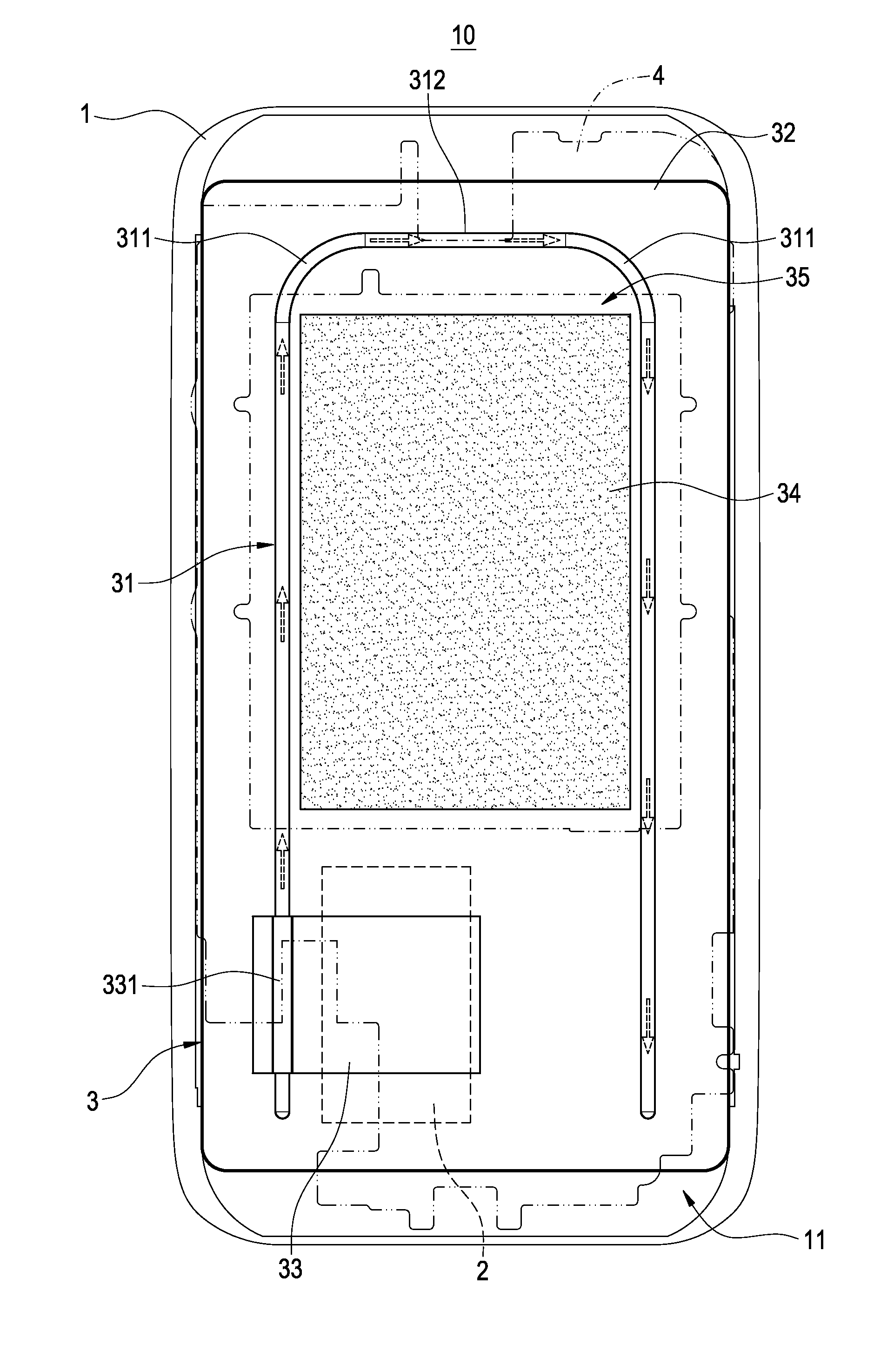
[0045]Please refer to FIG. 5 showing the handheld communication device of the present invention. As shown in the figure, the heat dissipator 3 further comprises an auxiliary heat conductive plate 34. The auxiliary heat conductive plate 34 is thermally attached to the heat conductive 32. The auxiliary conductive plate 34 can be made of a material such as graphite, ceramic or metal. According to a preferred embodiment of the present invention, the auxiliary heat conductive plate 34 is made of a graphite material.

[0046]Accordingly, the auxiliary heat conductive plate 34 is thermally attached to the heat conductive plate 32 such that efficiency of the heat dissipation of the heat dissipator 3 is enhanced and the heat dissipator 3 is able to even more uniformly dissipate the heat to the handheld communication device 10. As a result, the heat dissipator 3 of the present invention has an excellent efficiency of heat dissipation.

[0047]In addition, as the heat pipe 31 can be configured to ha...

third embodiment

[0048]Please refer to FIG. 6 showing the handheld communication device of the present invention. As shown in the figure, the aforementioned at least one bending section 311 includes a plurality of bending sections, and the heat pipe 31 includes a spiral-shaped pipe member 313 extended on one end thereof away from the heat generating unit 2. The plurality of bending sections 311 are formed on the spiral-shaped pipe member 313 such that the heat pipe 31 is able to wind on the heat conductive plate 32 over a large area in order to increase the contact area of thermal attachment between the heat pipe 31 and the heat conductive plate 32. As a result, the efficiency of the heat dissipation of the heat dissipator 3 can be enhanced.

fourth embodiment

[0049]Please refer to FIG. 7 showing the handheld communication device of the present invention. As shown in the figure, the aforementioned at least one bending section 311 includes one bending section, and the heat pipe 31 includes an L-shaped pipe member 314 extended on one end thereof away from the heat generating unit 2. The one bending section 311 is formed on the L-shaped pipe member 314 such that the heat pipe 31 is disposed on the heat conductive plate 32 with a bend in order to increase the contact area of thermal attachment between the heat pipe 31 and the heat conductive plate 32. As a result, the efficiency of the heat dissipation of the heat dissipator 3 can be enhanced.

[0050]In view of the above, the handheld communication device with heat dissipating structure of the present invention is able to achieve the objectives expected and to overcome the drawbacks of known arts, which is of novelty and inventive step to comply with the requirements of patentability and is app...


PUM


Abstract

A handheld communication device with a heat dissipating structure includes a housing, a heat generating unit and a heat dissipator. The housing includes a chamber formed therein; the heat generating unit is received inside the chamber; the heat dissipator is arranged corresponding to the heat generating unit. The heat dissipator includes a heat pipe and a heat conductive plate. The heat pipe includes one end thermally attached to the heat generating unit and another end arranged away from the heat generating unit, and the heat conductive plate is thermally attached to the heat pipe. With such structure, the heat generated by the heat generating unit can be uniformly conducted to the heat conductive plate in order to prevent the accumulation of heat at the surrounding of the heat generating unit and to improve the efficiency of the heat dissipation of the device.

Description

BACKGROUND OF THE INVENTION[0001]1. Field of the Invention[0002]The present invention is related to a handheld communication device, in particular, to a handheld communication device with a heat dissipating structure.[0003]2. Description of Related Art[0004]Handheld communication devices, including such as mobile phones, personal digital assistants (PDA), electronic readers and tablet computers, are developed to have greater computing powers and performances such that the internal components, including such as the central processors and integrated circuits, of modern handheld communication devices all generate a significant amount of heat during their operations, which needs to be dissipated effectively in order to maintain the proper operation and performance of these components as well as their useful lifetimes.[0005]Currently, a known heat dissipator utilized in a conventional handheld communication devices typically comprise a heat conductive plate made of a metal material in su...

Claims


Application Information

Patent Timeline
Patent Type & Authority Applications(United States)
IPC IPC(8): G06F1/20
CPCG06F1/203
Inventor YU, CHIA-HSINGWU, MING-CHIH
Owner CHAUN CHOUNG TECH
Why Eureka
Try Eureka