Sewing Machine Uplight Assembly

a technology for sewing machines and uplights, applied in sewing machines, sewing apparatuses, sewing machine elements, etc., can solve the problems of consuming usable space and failing to provide light, and achieve the effect of improving the visibility of the sewing area of the sewing machin

Inactive Publication Date: 2014-11-20
CASH JUDY
View PDF6 Cites 1 Cited by
  • Summary
  • Abstract
  • Description
  • Claims
  • Application Information

AI Technical Summary

Benefits of technology

[0017]In view of the foregoing disadvantages inherent in the known types of sewing machine light sources now present in the prior art, the present invention provides a new sewing machine uplight assembly, wherein the same can be utilized for improving visibility of the sewing area of the sewing machine.
[0020]Another object of the present invention is to provide a sewing machine light source that improves visual clarify of material work pieces at the needle contact area without interference from the user's hands or bunched material in the bed of the sewing machine.
[0021]Yet another object of the present invention is to provide a sewing machine light source that reduces mistakes and defects in the sewn material by improving visual clarity of the material and sewing area while the sewing machine is operational.
[0022]Another object of the present invention is to provide a sewing machine light source that improves efficiency of the sewing operation and reduces fatigue on the user.
[0025]A final object of the present invention is to provide a sewing machine light source that may be readily fabricated from materials that permit relative economy and are commensurate with durability.

Problems solved by technology

This arrangement provides improved downlighting on the work piece for a sewing machine while in use; however fails to provide light when the light is inevitably blocked by the user's hands or the material of the work piece becoming bunched above the needle during operation.
Overhead light sources suffer the aforementioned drawbacks of being easily blocked by the user's hands and by the material work pieces, while the positionable light is similarly disadvantaged by consuming usable space within the sewing area that may otherwise be necessary for movement of the material or movement of the reciprocating needle.

Method used


Image

  • Sewing Machine Uplight Assembly
  • Sewing Machine Uplight Assembly
  • Sewing Machine Uplight Assembly

Examples


Embodiment Construction

[0032]Reference is made herein to the attached drawings. Like reference numerals are used throughout the drawings to depict like or similar elements of the sewing machine uplight of the present invention. For the purposes of presenting a brief and clear description, the preferred embodiment will be discussed as used for improving the visual clarity of the sewing area of a sewing machine and improving the ability of the user to see material work pieces as they are stitched. The figures are intended for representative purposes only and should not be considered to be limiting in any respect.

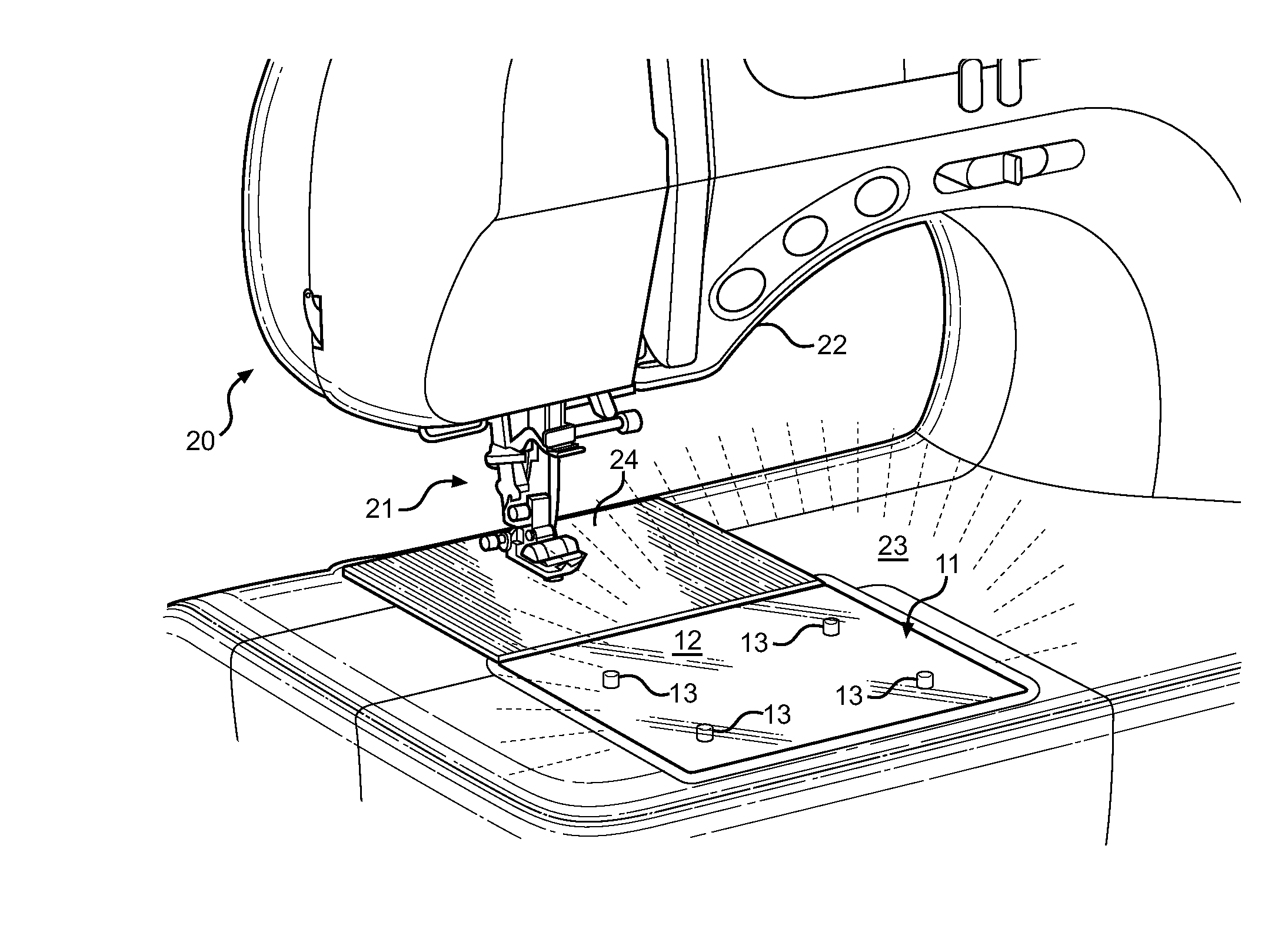
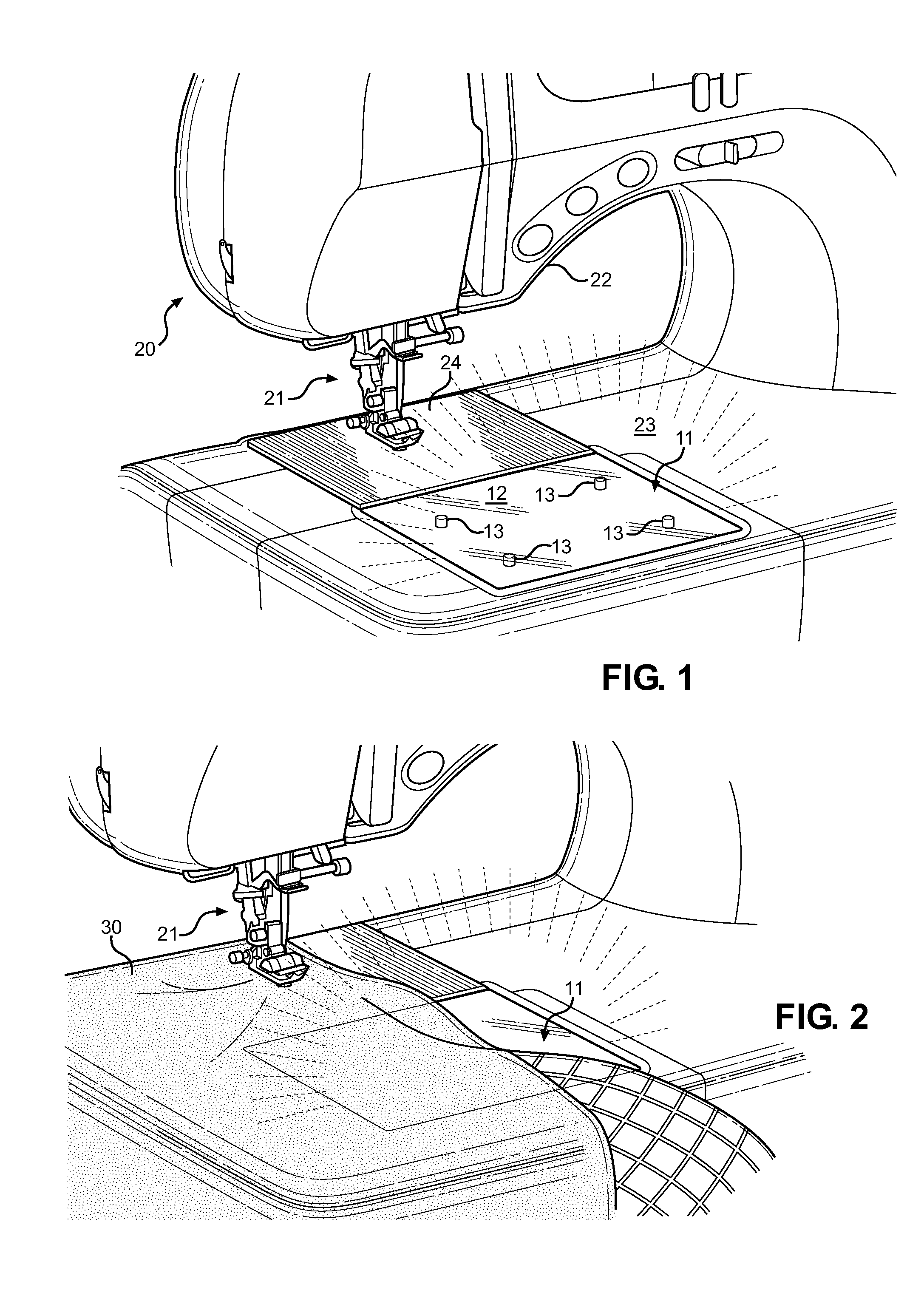
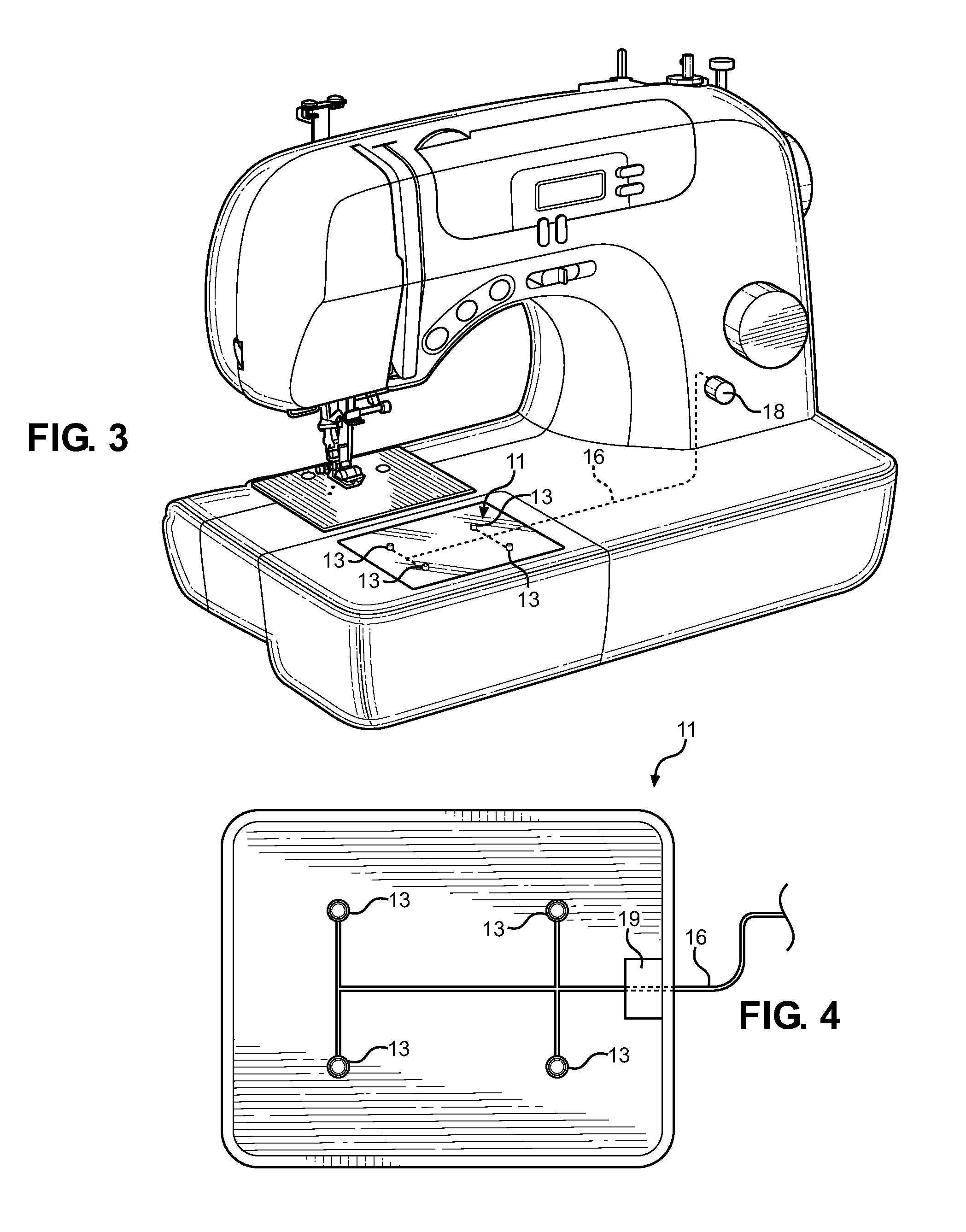
[0033]Referring now to FIG. 1, there is shown a close-up view of the sewing area of a typical sewing machine, wherein the uplight assembly 11 of the present invention is disposed along the bed 23 of the sewing area in front of the sewing machine throat plate 24. As with typical sewing machines, there is shown a sewing machine having an upper arm 20, a reciprocating needle and pressure foot 21, a thr...


PUM


Abstract

An uplight assembly for a sewing machine is provided, wherein the assembly is adapted to provide a light source along the bed of the sewing machine and adjacent to the throat plate thereof for projecting light from beneath a material work piece being sewn. The assembly comprises a transparent or translucent surface having at least one light source disposed thereunder, wherein the light source is controllable by the user. The activation of the light sources or the intensity of the light is adjustable by the user. The assembly is provided as an aftermarket assembly for existing sewing machines or as a new and novel uplight assembly adapted to be incorporated into a sewing machine bed design.

Description

CROSS REFERENCE TO RELATED APPLICATION[0001]This application claims the benefit of U.S. Provisional Application No. 61 / 824,232 filed on May 16, 2013, entitled “Blanket Light for Sewing Machine.” The above identified patent application is herein incorporated by reference in its entirety to provide continuity of disclosure.BACKGROUND OF THE INVENTION[0002]1. Field of the Invention[0003]The present invention relates to sewing machines and improved lighting therefor. More specifically, the present invention relates to a new lighting system for a conventional sewing machine that allows the user to better see the material and the stitching as the material is fed through the machine.[0004]Sewing machines are well known in the art for the purposes of stitching material and for creating garments using needle and thread, wherein the stitching operation is automated as the user guides the material into a reciprocating needle and thread. Modern sewing machines consist of several common elements...

Claims


Application Information

Patent Timeline
Patent Type & Authority Applications(United States)
IPC IPC(8): D05B79/00
CPCD05B79/00
Inventor CASH, JUDY
Owner CASH JUDY
Why Eureka
Try Eureka