
Method And Apparatus For Optical Transmission In A Communication Network

a communication network and optical transmission technology, applied in the field of communication networks, can solve problems such as affecting the wavelength at which the laser is transmitted, and achieve the effect of reducing or alleviating the detrimental or undesirable effects

Inactive Publication Date: 2014-11-20
ALCATEL LUCENT SAS +1
View PDF10 Cites 22 Cited by
  • Summary
  • Abstract
  • Description
  • Claims
  • Application Information

AI Technical Summary

Benefits of technology

The patent is about preventing a laser or other light source from heating up during use in a communication network. This is done by reducing or minimizing the detrimental effects of self heating, which can occur during the initial stages of a transmission. The technical effect is to improve the performance and reliability of communication networks.

Problems solved by technology

An operating laser will often generate heat itself, however, and this may affect the wavelength at which the laser is transmitting.

Method used


Image

  • Method And Apparatus For Optical Transmission In A Communication Network
  • Method And Apparatus For Optical Transmission In A Communication Network
  • Method And Apparatus For Optical Transmission In A Communication Network

Examples


Embodiment Construction

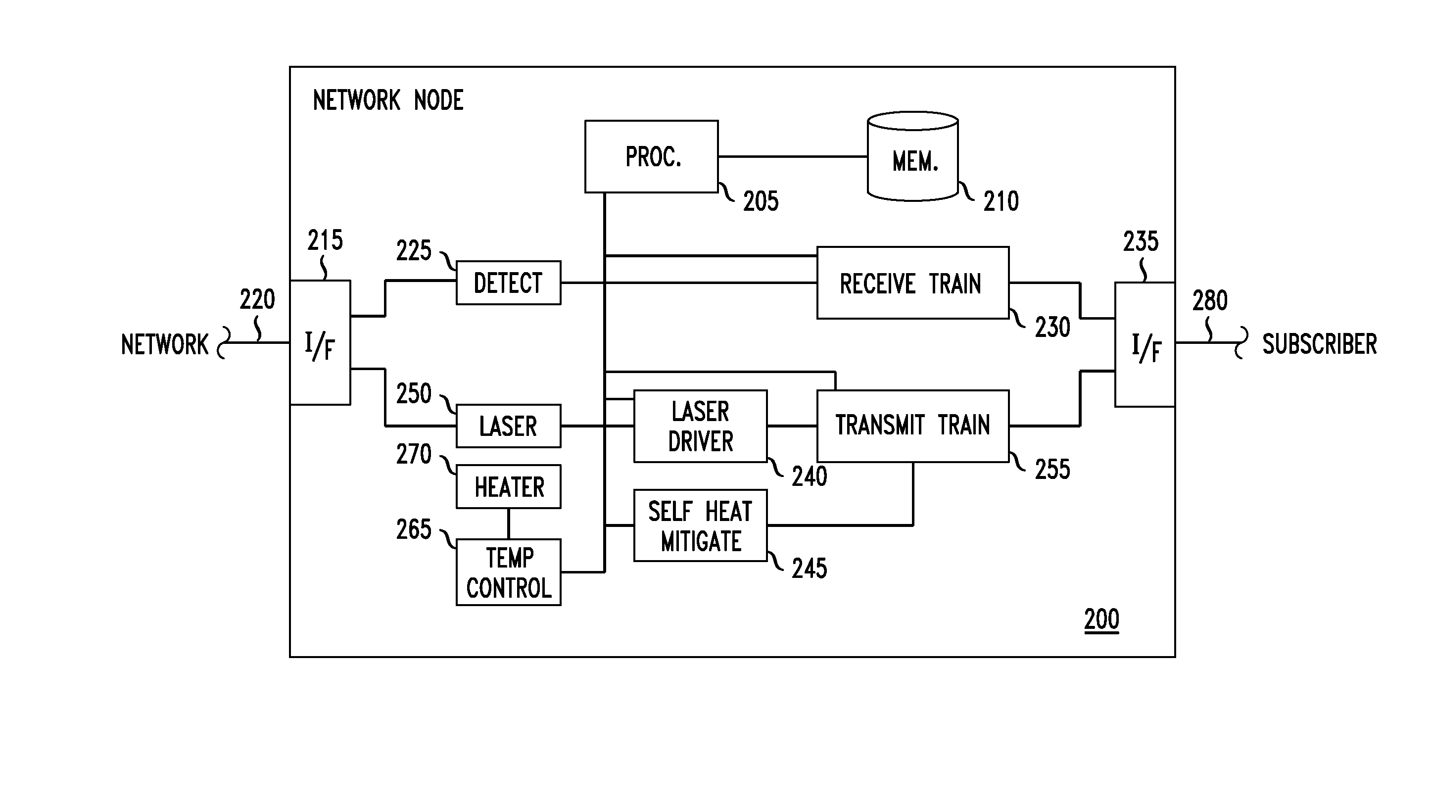
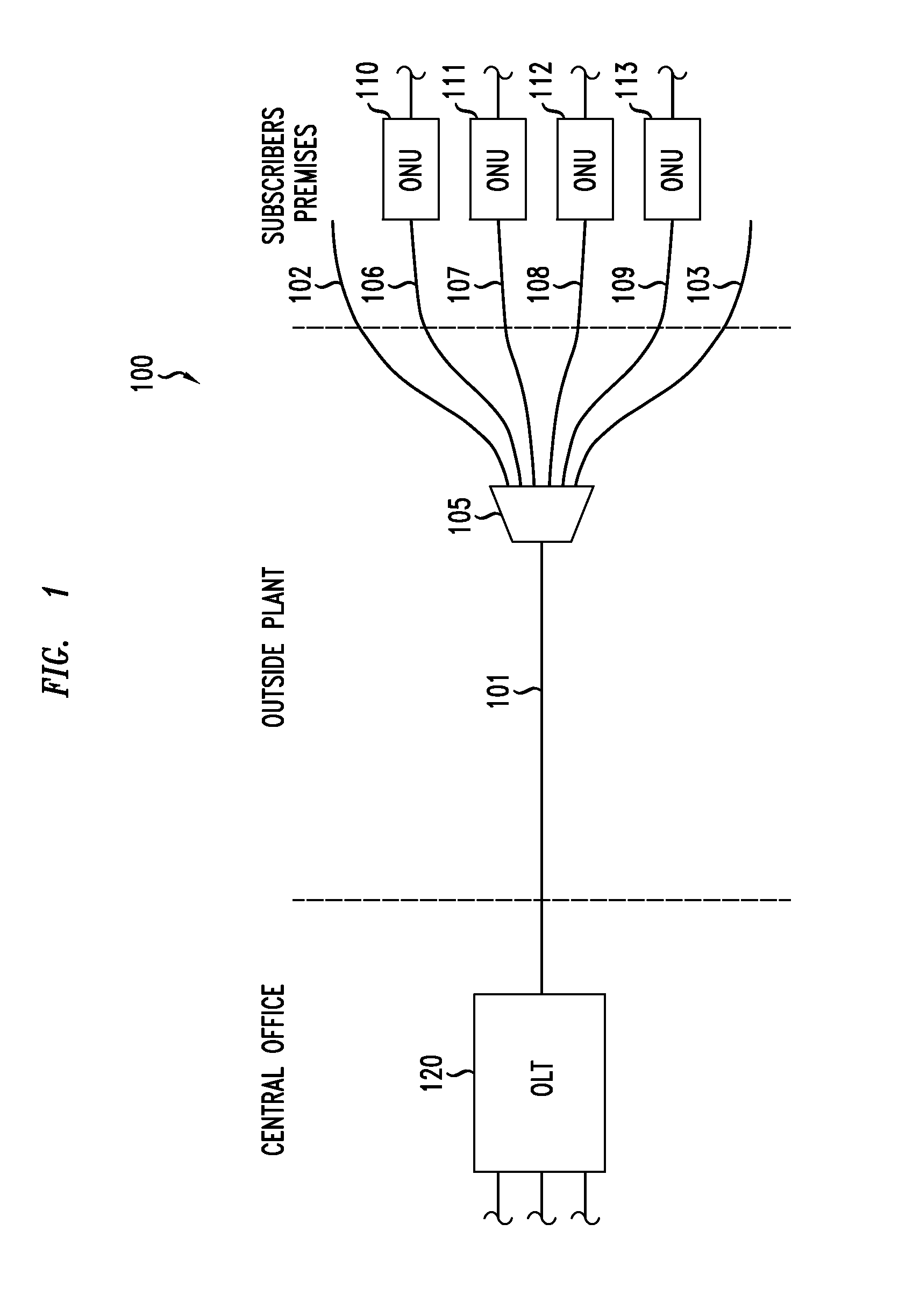
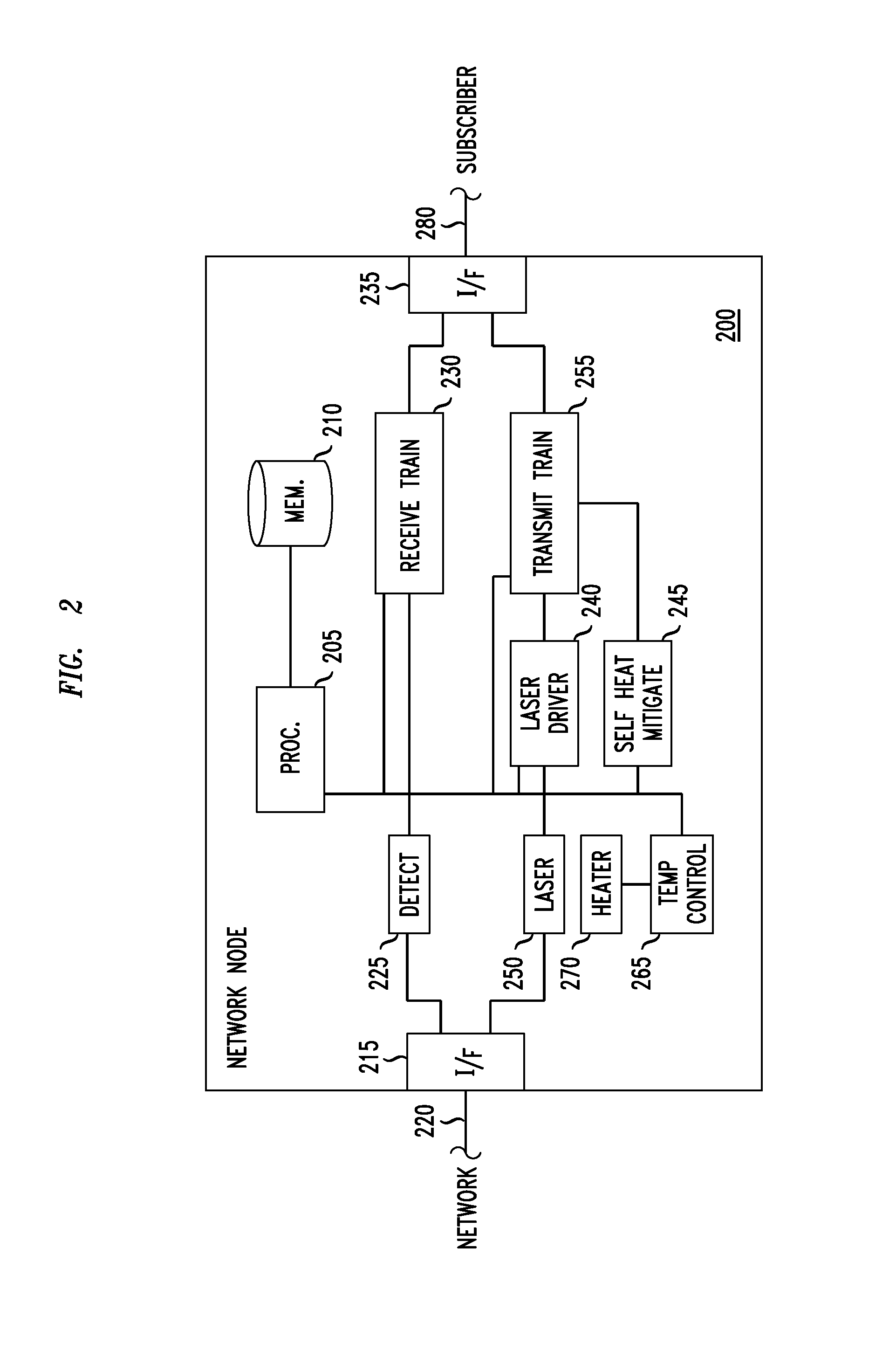
[0032]The present invention is directed to an apparatus and method for sending optical transmissions in a communication network. The method is expected to be of particular advantage when implemented in an ONU (optical network unit) of a PON (passive optical network), and will be herein described in those terms even though some or all aspects of the invention may be implemented in other environments as well. A PON for implementing the present invention will now be described in more detail.

[0033]FIG. 1 is schematic diagram illustrating selected components of a PON 100 in which embodiments of the present invention may be advantageously implemented. Note that PON 100 may, and in many implementations will, include additional components, and the configuration shown in FIG. 1 is intended to be exemplary rather than limiting. Four ONUs, 110 through 113, are shown, although in a typical PON there may be many more or, in some cases, fewer. In this illustration, each of the ONUs are presumed t...


PUM


Abstract

A manner of mitigating the self heating effect of a laser or other light source such as a laser in a network node of a communication network. A self-heating mitigation module is provided, the self-heating mitigation module includes one or both of a self-heating adjustment module to accelerate self heating at the beginning of a transmission and a sub-threshold lasing module that applies a sub-threshold current between transmissions. The self-heating adjustment module and the sub-threshold lasing module are preferable both used together and driven by a common signal, for example the burst_enable signal that facilitates transmission from the light source.

Description

CROSS-REFERENCE TO RELATED APPLICATIONS[0001]The present disclosure is related to and claims priority from U.S. Provisional Patent Application Ser. No. 61 / 823,979 entitled Mitigation of Burstmode Laser Wavelength Drift due to Selfheating and filed on 16 May 2013, and U.S. Provisional Patent Application Ser. No. 61 / 824,320 entitled Mitigation of Wavelength Drift due to Self-Heating of Directly-Modulated Burstmode Laser and filed on 16 May 2013, the entire contents of which applications are incorporated by reference herein.TECHNICAL FIELD[0002]The present invention relates generally to the field of communication networks, and, more particularly, to a method and apparatus for sending optical transmission in an optical communication network, for example a passive optical access network.BACKGROUND[0003]The following abbreviations are herewith expanded, at least some of which are referred to within the following description of the state-of-the-art and the present invention.[0004]CO Centra...

Claims


Application Information

Patent Timeline
IPC IPC(8): H04B10/50H04B10/564
CPCH04B10/564H04B10/503H04B10/272H04B10/504
Inventor VAN VEEN, DOUTJE T.FARAH, ROBERTVETTER, PETERPOEHLMANN, WOLFGANG
Owner ALCATEL LUCENT SAS
Learn More