Profiled frame element

Inactive Publication Date: 2014-11-20
PATEA
View PDF2 Cites 3 Cited by
  • Summary
  • Abstract
  • Description
  • Claims
  • Application Information

AI Technical Summary

Benefits of technology

The invention provides a frame profile that can be attached to a longitudinal profile, allowing for the creation of walls that extend beyond the width of the longitudinal profile. The frame profile can be made from metal or plastic and can be attached to the longitudinal profile using a detachable connection. The frame profile has a main member and a guide lug that interacts with a groove in the longitudinal profile. The guide lug has an offset, allowing for different wall depths to be accommodated. The technical effect of the invention is the creation of a versatile and flexible frame profile that can be easily attached to a longitudinal profile for the creation of walls in various situations.

Problems solved by technology

The exhibition walls thus realized however generally do not offer adequate insulation action, or entail disproportionately high outlay.
A disadvantage of the prior art is that the erection and dismantling of exhibition walls is relatively expensive, and the scope for the use of creative possibilities is severely limited.
A further disadvantage of the prior art is that the erection and dismantling of walls in room-in-room systems is cumbersome and relatively expensive, and furthermore, meaningful scope for creative variety is severely limited.
Furthermore, the devices known from the prior art meet the modern demands only to a certain extent.
Furthermore, the devices known from the prior art likewise do not meet modern demands with regard to design.

Method used


Image

  • Profiled frame element
  • Profiled frame element
  • Profiled frame element

Examples


Embodiment Construction

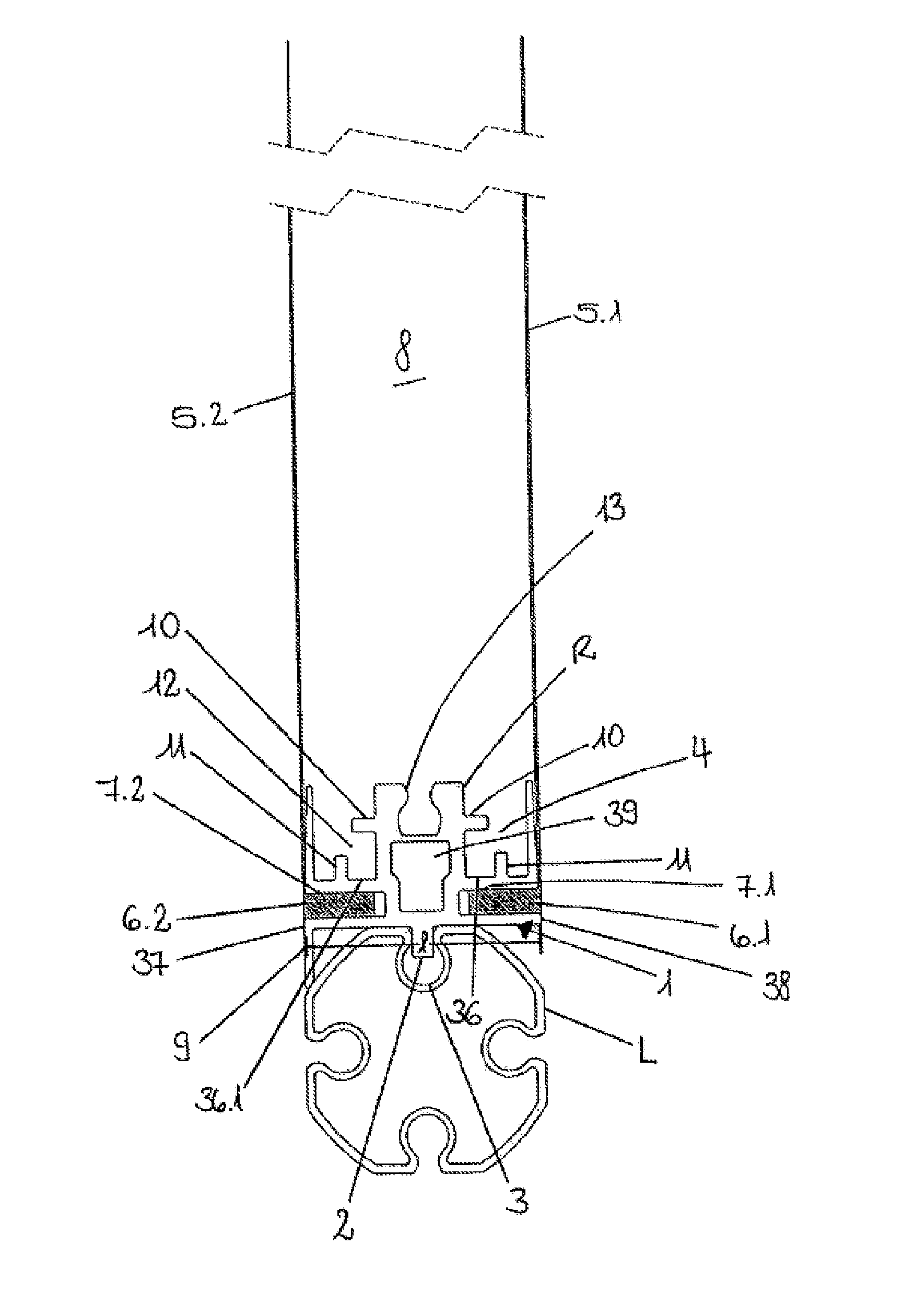
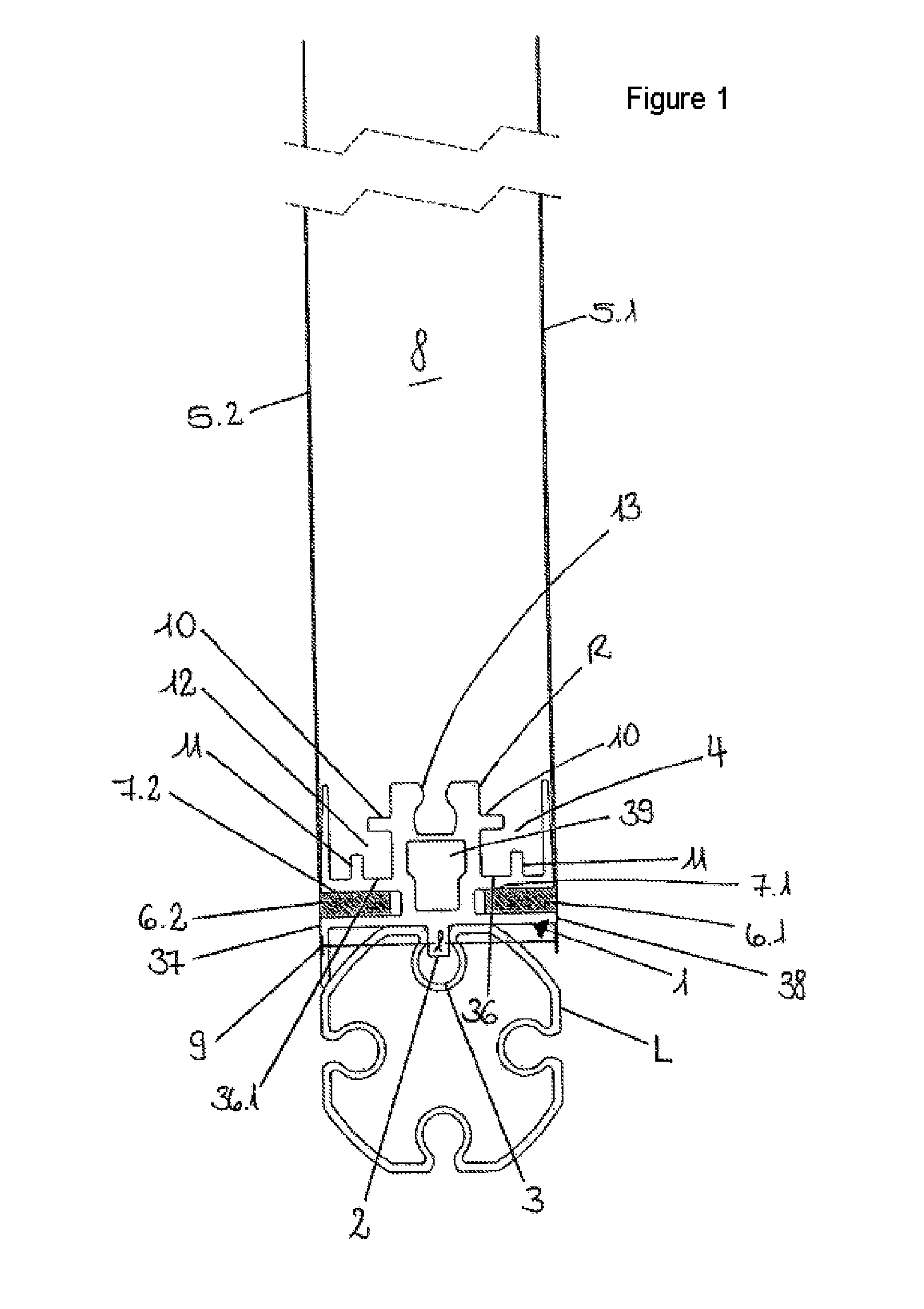
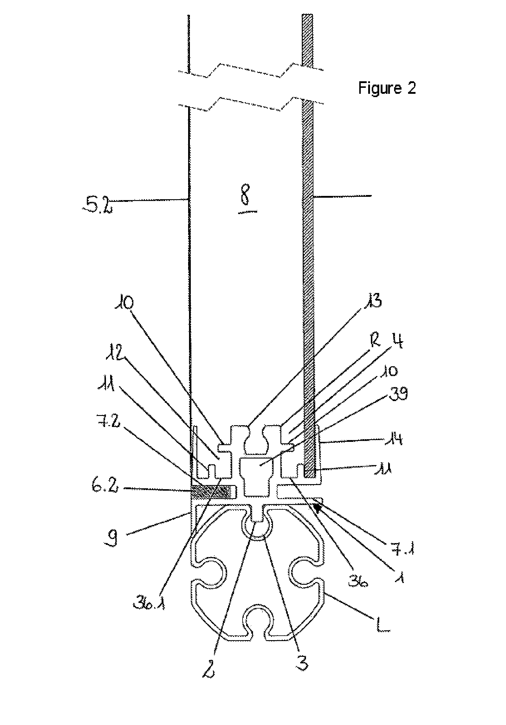
[0043]FIG. 1 shows an exemplary embodiment of a frame profile R according to the invention. Said frame profile R serves for attachment to a longitudinal profile L. For this purpose, a main member 1 is provided. On said main member 1 there is formed a guide lug 2. In FIG. 1, the guide lug 2 projects into a groove 3 of the longitudinal profile L. Furthermore, the frame profile R has a slot 4 for different wall thicknesses of solid wall fillings. It can also be seen how in each case one textile wall 5.1, 5.2 can be connected to the frame profile R by insertion of a flat welt 6.1 and 6.2 into a groove 7.1 and 7.2. The flat welt 6.1, 6.2 forms a unit with the textile wall 5.1, 5.2. The intermediate space 8 between the textile walls 5.1, 5.2 can be used for accommodating various insulation elements. The intermediate space 8 may however also be implemented without the use of insulation elements. FIG. 1 also shows how a faceplate 9 is formed on the main member 1. Said faceplate 9 is formed ...


PUM


Abstract

A profiled frame element to be mounted on a longitudinal profiled element (L) having at least one groove (3). The profiled frame element (R, R1) has a bottom support (1) and a guiding projection (2). At least one channel (4) is provided which is suitable for accommodating different wall thicknesses.

Description

BACKGROUND OF THE INVENTION[0001]The invention relates to a frame profile for attachment to a longitudinal profile and to a cladding profile.[0002]The prior art has disclosed longitudinal profiles with grooves which are used as corner pillars of exhibition walls. For this purpose, the exhibition walls are inserted into the groove. The exhibition walls thus realized however generally do not offer adequate insulation action, or entail disproportionately high outlay. In general, use is made of simple plastics panels or textile walls which are connected directly to the corner pillars. The so-called corner pillars will be referred to as longitudinal profiles throughout the remainder of the patent application. The prior art has disclosed a combination of textile and solid walls, in particular of different wall depths.[0003]A disadvantage of the prior art is that the erection and dismantling of exhibition walls is relatively expensive, and the scope for the use of creative possibilities is...

Claims


Application Information

Patent Timeline
IPC IPC(8): E04D3/36E04B2/78
CPCE04B2/78E04D3/36E04B2/7433E04B2/7854E04B2002/7479E04H1/1272Y10T403/70Y10T403/7062
Inventor STOECKLER, HEINZ
Owner PATEA
Why Eureka
Try Eureka