Method and a device for computer assisted surgery

Active Publication Date: 2014-11-20
SYNTHES GMBH
View PDF9 Cites 21 Cited by
  • Summary
  • Abstract
  • Description
  • Claims
  • Application Information

AI Technical Summary

Benefits of technology

[0017]It is an object of the invention to provide a method and a medical device permitting to position the medical device relative to a target structure or to a reference base by means of a computer, wherein the

Problems solved by technology

One problem associated with the above described computer assisted surgery system and the method of using the same can be that the position of an implant or a surgical instrument is determined on the basis of a separate reference body comprising a plurality of markers which has to

Method used


Image

  • Method and a device for computer assisted surgery
  • Method and a device for computer assisted surgery
  • Method and a device for computer assisted surgery

Examples


Example

Example 1

Placement of an Intramedullary Hip Implant

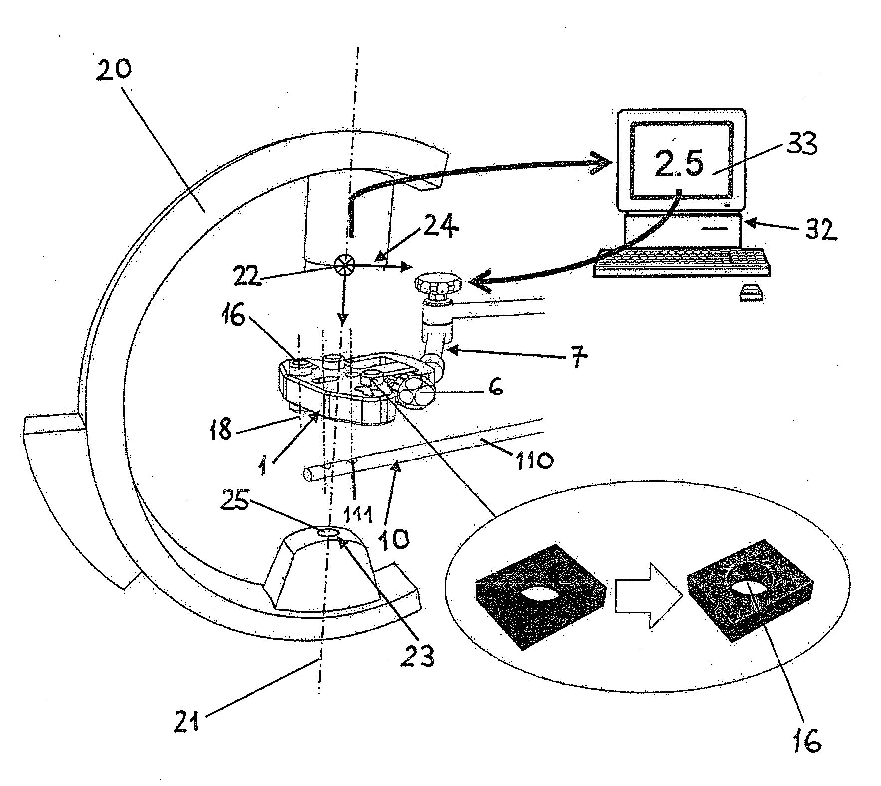
[0145]Intramedullary hip implants are frequently used for treatment of proximal femur fractures. An intramedullary nail 110 is inserted into the intramedullary channel of the femur and a hip screw 510 or blade is inserted through the intramedullary nail 110 into the femoral head 520 (FIG. 5). Particular in porotic bone, accurate placement of this hip screw 510 is important for stable fixation. To achieve positioning in the center of the femoral head 520, current practice involves repeated radiology in two orthogonal planes. Position of the intramedullary nail 110 can be adjusted in two degrees of freedom, namely the nail insertion depth and the rotation about the nail axis.

[0146]To simplify this procedure the medical device 1 according to the invention comprises an implant or a nail insertion handle 8 with cylindrical reference means 16. From two oblique (not necessarily orthogonal) X-ray images displaying the projections of the cyl...

Example

Example 2

Anatomical Fracture Reduction: Adjusting Leg Rotation

[0147]A common complication after intramedullary nailing of a long bone is malrotation of the injured limb. A bone fragment can freely rotate about the axis of an intramedullary nail 110. For the operator it is difficult to define the anatomical orientation of this fragment from a plain X-ray projection.

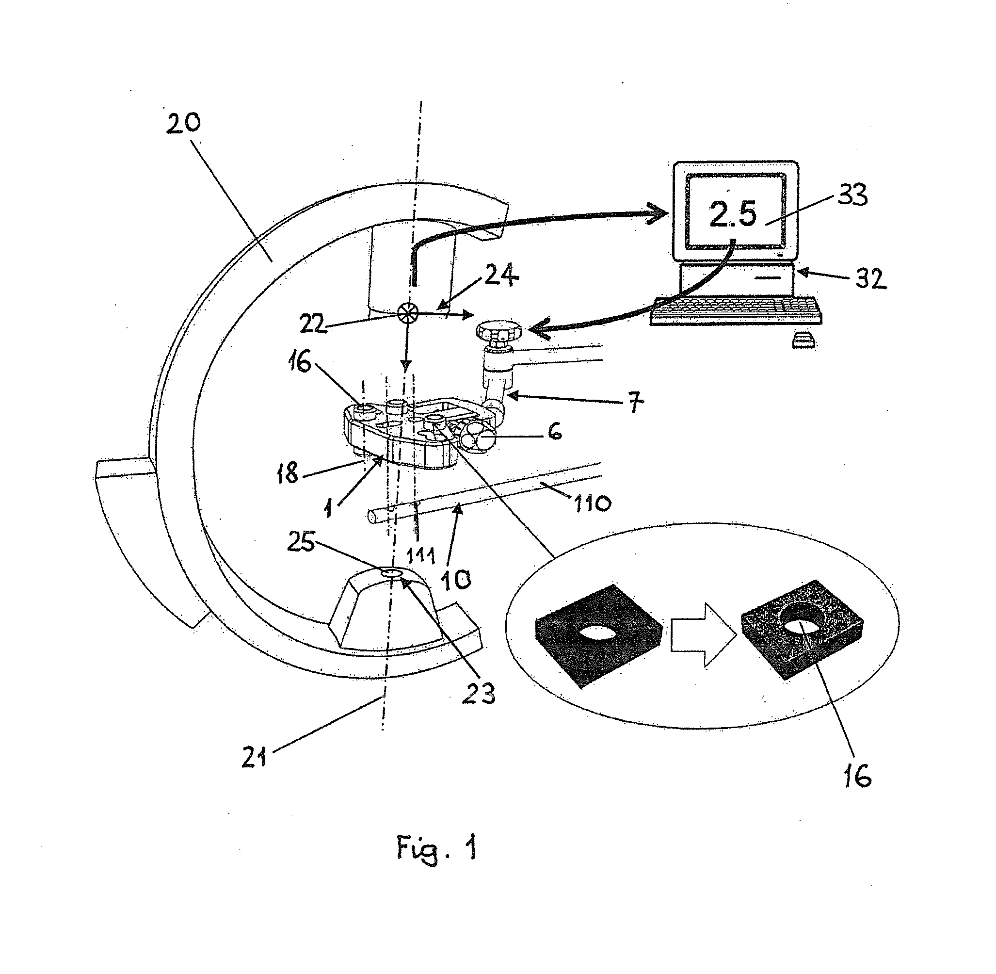
[0148]The method and device according to the invention allow adjusting for example the orientation of a distal femur fragment with respect to the proximal femur fragment before locking the intramedullary nail 110 into place. A medical device 1 according to FIG. 2 without the need for guiding structures 5 or mechanical means 6 is rigidly attached to the insertion handle 8 of a femur intramedullary nail 110 with known orientation between medical device 1 and the intramedullary nail 110. The medical device 1 can be a rigid arm with cylindrical reference means 16 attached to a handle 8. Preferably, a medical device 1 according...

Example

Example 3

Distal Interlocking of Intramedullary Nails

[0149]Locking an intramedullary nail 110 distally in place is difficult since the intramedullary nail 110 deflects inside the intramedullary channel. The position of the distal interlocking holes 111 (FIG. 1) cannot be predicted from the outside for reliably drilling and inserting the transverse locking bolts.

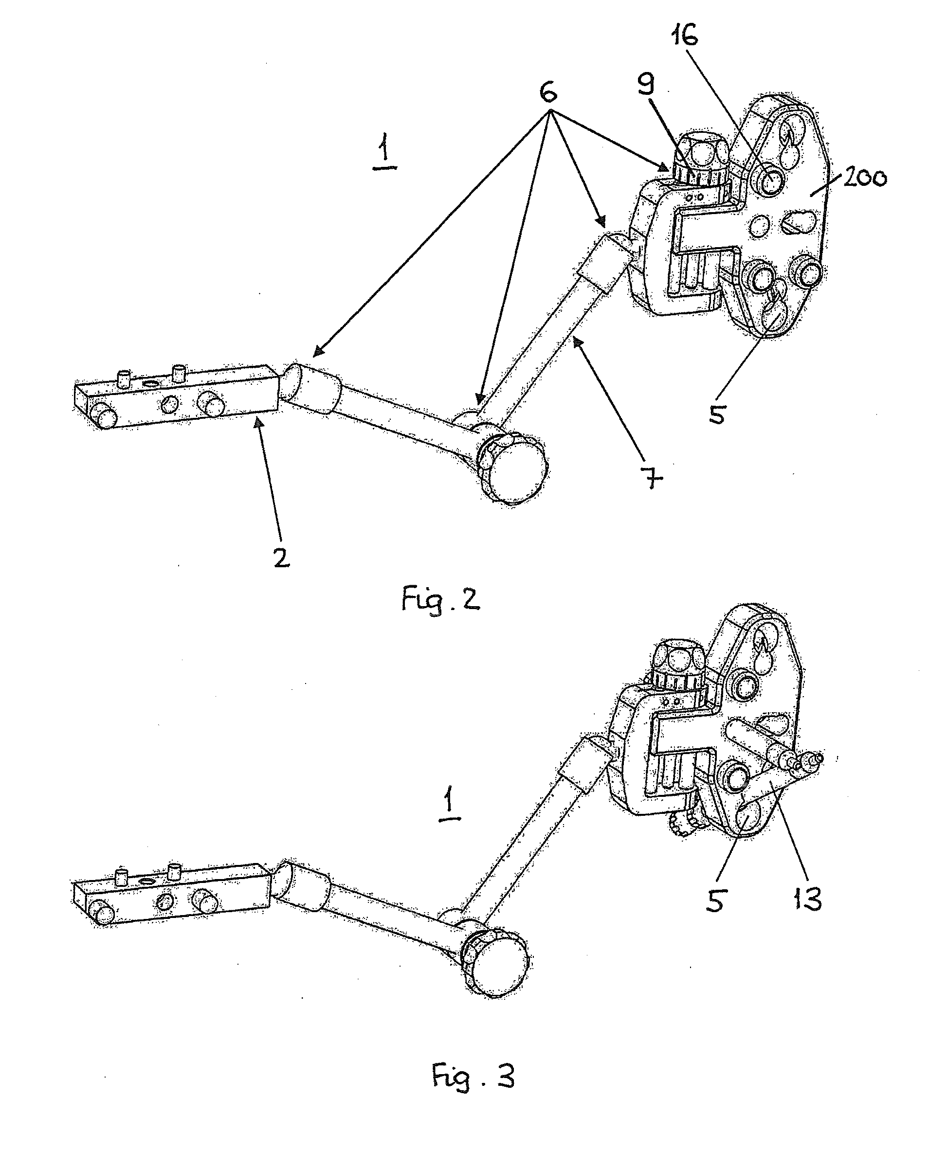
[0150]The method and device according to the invention permits to solve the above problem by use of a medical device 1 according to FIGS. 2 and 3 rigidly attached to an insertion handle 8 of an intramedullary nail 110 analog to example 2. In addition the medical device 1 comprises guiding structures 5 matching with the interlocking pattern of the intramedullary nail 110 to receive and guide a drill-bit and an interlocking bolt. Furthermore, the medical device 1 allows defined mechanical adjustment in two degrees of freedom, namely two translations in a plane normal to the drilling axis or one translation and one rotation about...


PUM


Abstract

A method for computer assisted determination of values of correction parameters for positioning a medical device relative to a target structure or to a reference base. The method includes a numerical procedure that includes the steps of:
    • i) automatic detection of the projection of a cylindrical reference means in a medical image and determination of a minimum of four characteristic landmarks within the projection of the cylindrical reference means;
    • ii) generating a virtual geometric representation of the cylindrical reference means;
    • iii) determining the virtual projection points representing the characteristic landmarks using a virtual geometric representation of the cylindrical reference means; and
    • iv) iterative determination of the position and orientation of the cylindrical reference means by matching the virtual projection points of the virtual geometric representation of the cylindrical reference means with the characteristic landmarks of the projection of the cylindrical reference means.

Description

BACKGROUND OF THE INVENTION[0001]1. Field of the Invention[0002]The invention relates to a method for computer assisted determination of positioning parameters for positioning of a medical device relative to a target structure according to the preamble of claim 1 and to a medical device for use with the method according to the preamble of claim 32.[0003]The task of placing implants plays a key role in trauma and orthopedics as well as in several other medical disciplines. Not only with upcoming minimal invasive techniques, orientation in anatomical terrain is demanding and requires experience of the operator. Prolonged surgery time accompanied by intense radiation and poor surgical results are the consequence. Computer assisted surgery (CAS) concepts aim at easing surgical handling. They are generally based on a three step approach where in a first step medical imaging of the region of interest is required, secondly a virtual surgical plan of the operation is generated and in a thir...

Claims


Application Information

Patent Timeline
IPC IPC(8): A61B19/00
CPCA61B19/2203A61B2019/5466A61B19/5244A61B17/1703A61B17/1721A61B17/1725A61B17/1728A61B17/1753A61B34/32A61B34/20A61B2090/376A61B90/37A61B2034/2065A61B90/39A61B2090/3966A61B17/1778A61B2017/00818A61B34/30
Inventor WINDOLF, MARKUSNOTZLI, CHRISTOPH MARTIN
Owner SYNTHES GMBH
Why Eureka
Try Eureka