Electromagnetically actuatable valve

Active Publication Date: 2014-11-27
ROBERT BOSCH GMBH
View PDF11 Cites 18 Cited by
  • Summary
  • Abstract
  • Description
  • Claims
  • Application Information

AI Technical Summary

Benefits of technology

[0003]The electromagnetically actuatable valve according to the present invention for controlling fluids has, in contrast, the advantage that an additional damping and reduction of an impact impulse is possible. In addition, according to the present invention an improved wear characteristic of the valve can be achieved. According to the present invention, this is achieved in that an inner pole and a magnetic armature each have an end face directed toward one another, the end faces being shaped in such a way that a first and second contact line are present between the two end faces when the inner pole and the magnetic armature

Problems solved by technology

As a result, during operation wear can occur, so that the components subject to wear

Method used


Image

  • Electromagnetically actuatable valve
  • Electromagnetically actuatable valve
  • Electromagnetically actuatable valve

Examples


Embodiment Construction

[0019]In the following, a fuel injection valve 1 according to a first exemplary embodiment of the present invention is described in detail with reference to FIGS. 1 through 3.

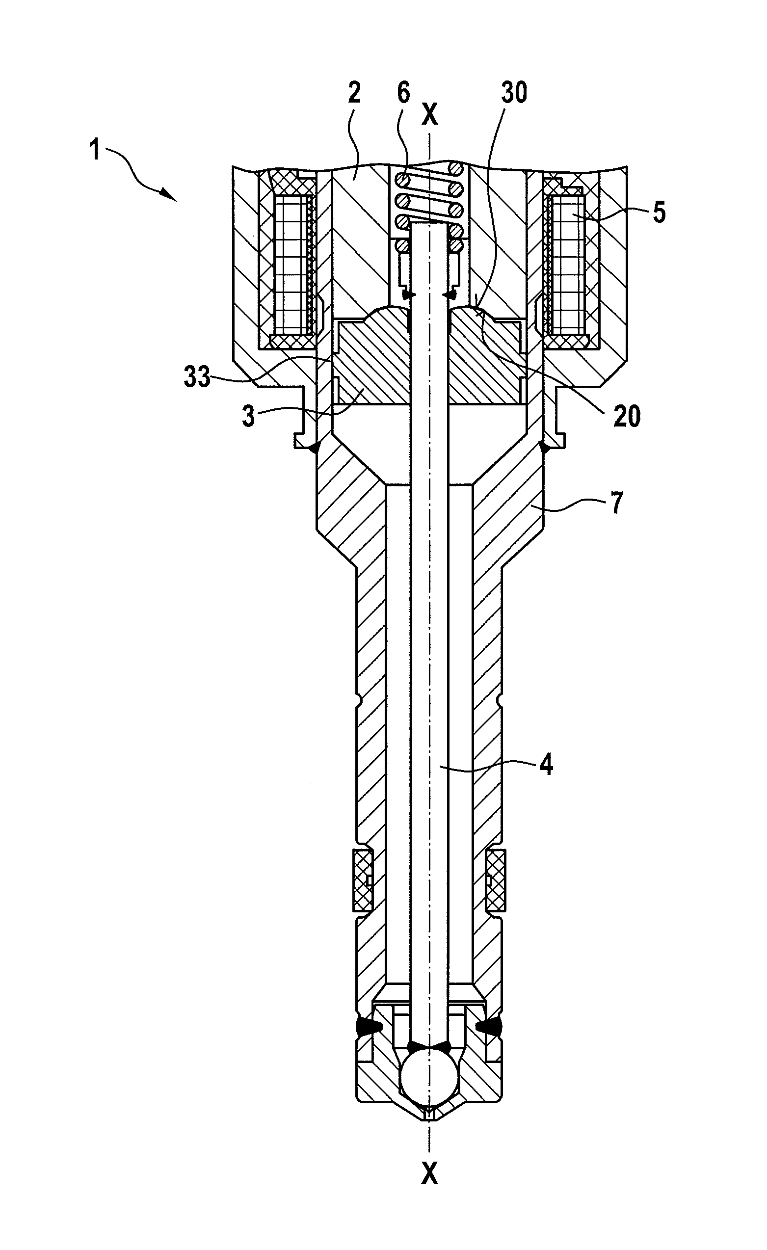
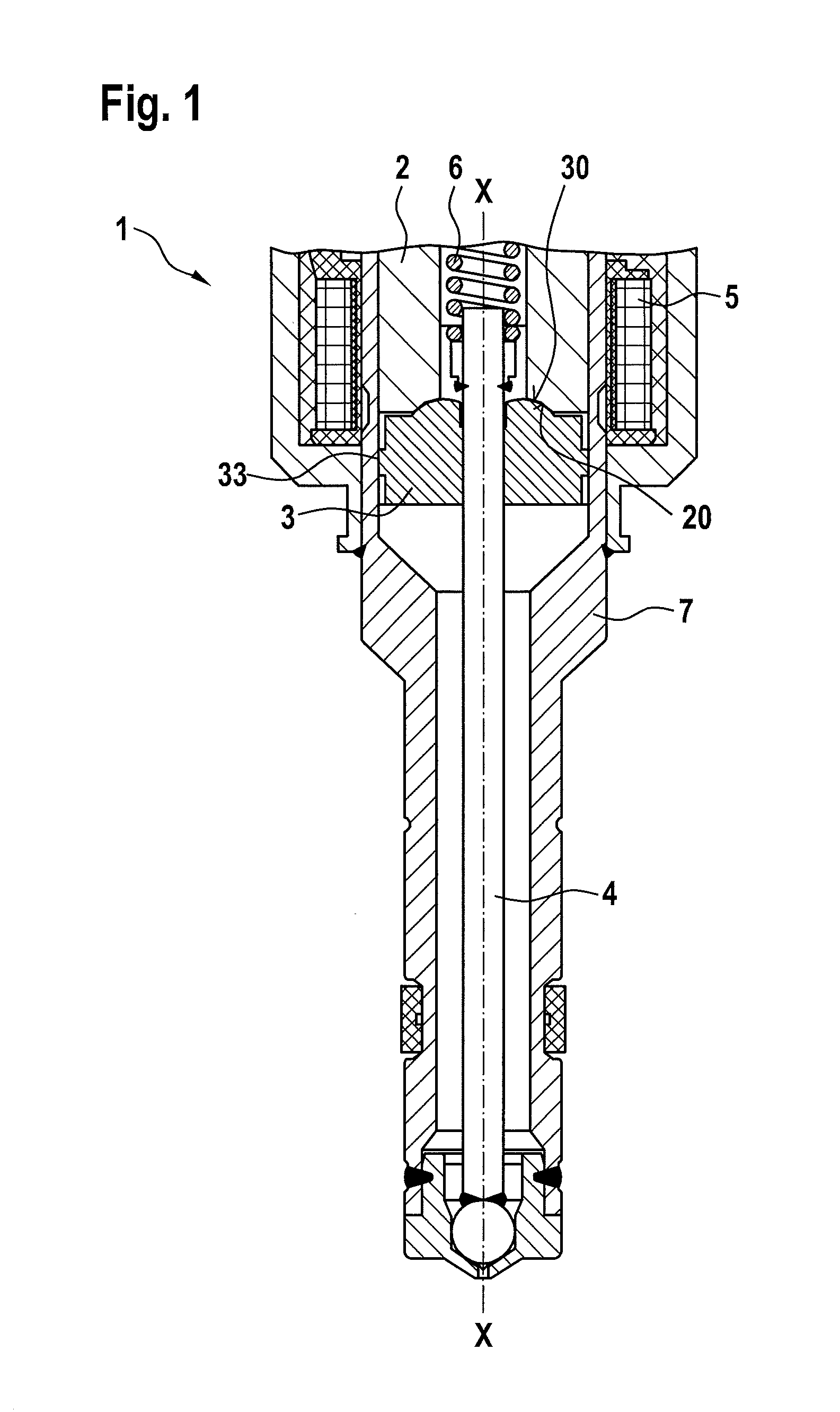
[0020]As can be seen from FIG. 1, fuel injection valve 1 includes an inner pole 2, a magnetic armature 3, and a coil 5. In addition, a valve needle 4 is provided that is connected to magnetic armature 3. A resetting spring 6 resets valve needle 4 to the initial position shown in FIG. 1, in which fuel injection valve 1 is closed. Reference character 7 designates a housing of the fuel injection valve.

[0021]In order to actuate the fuel injection valve, in a known manner coil 5 is supplied with current, causing magnetic armature 3 to be drawn toward inner pole 2, and, given a maximum opening demand of the injection valve, to impact against inner pole 2. FIG. 1 shows the closed state of the valve.

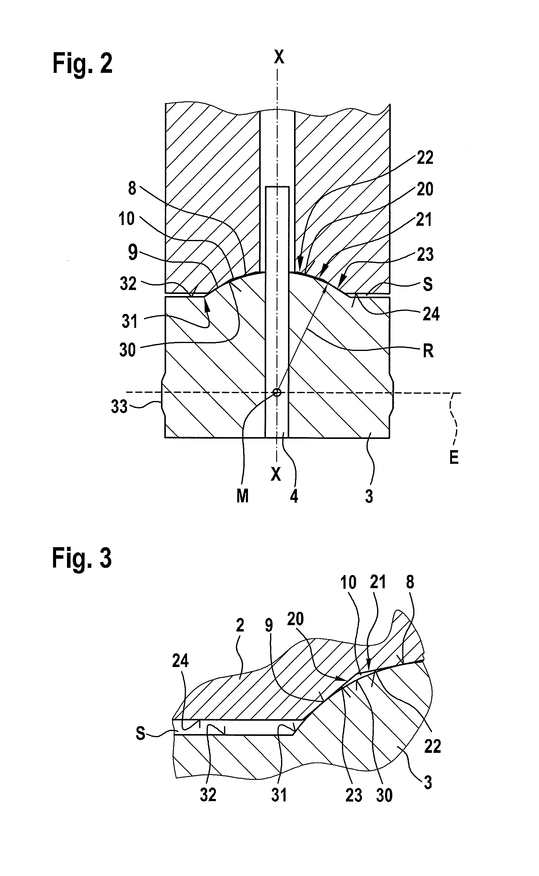
[0022]The construction of inner pole 2 and of magnetic armature 3 is shown in detail in FIGS. 2 and 3. As can be seen in ...


PUM


Abstract

An electromagnetically actuatable valve is described, for controlling fluids, having an inner pole and a magnetic armature, the inner pole having a first end face oriented to the magnetic armature, and the magnetic armature having a second end face oriented to the inner pole, a first contact line and a second contact line being present between the first and second end face when the inner pole and the magnetic armature come into contact with one another, and a damping volume being present between the first and second contact line when the inner pole and the magnetic armature come into contact with one another.

Description

FIELD OF THE INVENTION[0001]The present invention relates to an electromagnetically actuatable valve for controlling fluids, in particular fuel.BACKGROUND INFORMATION[0002]Valves are known from the existing art in various embodiments. In fuel injection valves, electromagnetically actuatable valves are often used in which a magnetic armature is attracted by an inner pole. When this happens, the magnetic armature can impact against the inner pole or against a stop. As a result, during operation wear can occur, so that the components subject to wear are often provided with a wear-resistant layer, for example made of chrome or nickel. In addition, from German Published Patent Application No. 198 33 461 a magnetic valve is known in which the components that impact one another, the magnetic armature and the inner pole, are made in such a way that one of the components that strike one another has a spherically curved surface. This design has proved effective, but it would be desirable if a...

Claims


Application Information

Patent Timeline
IPC IPC(8): F16K31/06
CPCF16K31/06F02M51/0671F02M51/0664F02M51/0614F02M2200/304F02M2200/09F02M2200/02
Inventor SCHEFFEL, MARTINROGLER, PHILIPPABEL, JOERGPOHLMANN, JENSMASSONI, ANNA SALVAT
Owner ROBERT BOSCH GMBH
Why Eureka
Try Eureka