Active air flap device for vehicles

a technology of active air flaps and vehicles, which is applied in the direction of roofs, transportation and packaging, vehicle arrangements, etc., can solve the problems of limited improvement of aerodynamic performance and mileage of vehicles, inconvenient for users, and inability to provide desired air blocking rate of active air flap devices, so as to improve the aerodynamic performance of vehicles and reliably provide the minimum cooling surface area

Active Publication Date: 2014-11-27
HYUNDAI MOTOR CO LTD
View PDF1 Cites 16 Cited by
  • Summary
  • Abstract
  • Description
  • Claims
  • Application Information

AI Technical Summary

Benefits of technology

[0012]Accordingly, the present invention has been made keeping in mind the above problems occurring in the related art, and the present invention is intended to propose an active air flap device for vehicles which can appropriately control the air blocking rate that can block air flowing from the front of a vehicle when the vehicle is being driven, thereby improving the aerodynamic performance of the vehicle, and which can provide a sufficient cooling surface area required to cool a variety of cooling systems when the vehicle is being stopped, thereby reliably providing the minimum cooling surface area without forcing a user to separately manipulate air flaps when a system-fail is generated, and so the active air flap device can provide improved driving efficiency and improved driving safety.

Problems solved by technology

However, in the first type of active air flap device, the active air flap is installed in only one of the upper and lower parts of the air intake unit, and so the active air flap device cannot provide a desired air blocking rate, thereby being limited with regards to improvement of the aerodynamic performance and mileage of a vehicle.
However, the second type of active air flap device is problematic in that, when the system of this active air flap device malfunctions in a state in which the upper and lower active air flaps are closed, a user should manually open the flaps after stopping the vehicle and this is inconvenient to the user.
Further, the operation of manually opening the flaps is difficult, and so it is not easy to manually open the flaps.
Further, when the flaps are not opened, it causes a critical problem in that the vehicle may not be driven.
However, the technique disclosed in Korean patent application publication No. 10-2012-0106034 is problematic in that it cannot improve the aerodynamic performance of a vehicle, thereby failing to increase the mileage of the vehicle.

Method used


Image

  • Active air flap device for vehicles
  • Active air flap device for vehicles
  • Active air flap device for vehicles

Examples


Embodiment Construction

[0030]Reference will now be made in detail to various embodiments of the present invention(s), examples of which are illustrated in the accompanying drawings and described below. While the invention(s) will be described in conjunction with exemplary embodiments, it will be understood that present description is not intended to limit the invention(s) to those exemplary embodiments. On the contrary, the invention(s) is / are intended to cover not only the exemplary embodiments, but also various alternatives, modifications, equivalents and other embodiments, which may be included within the spirit and scope of the invention as defined by the appended claims.

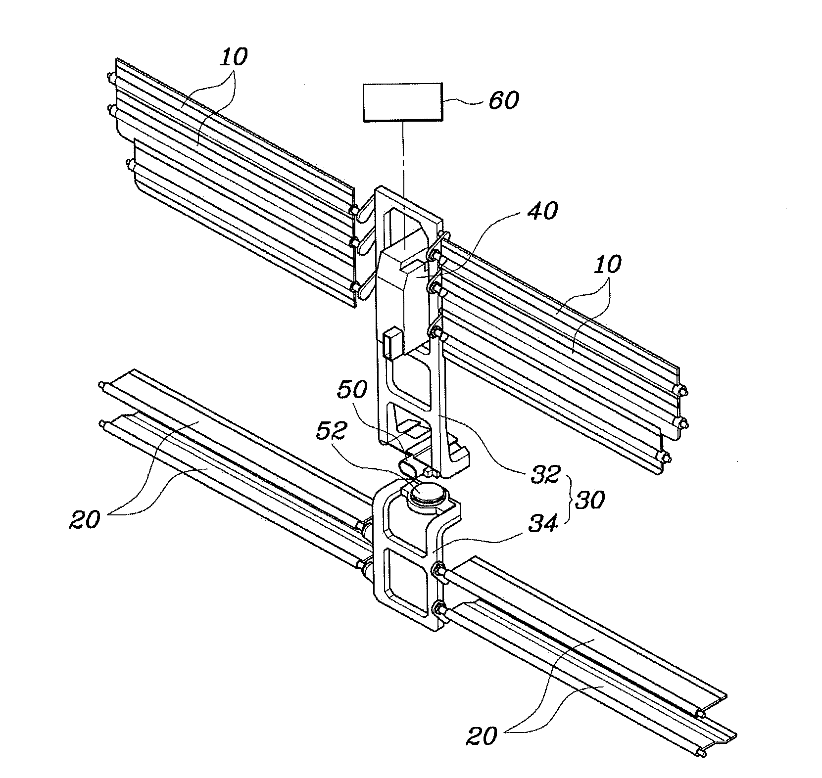
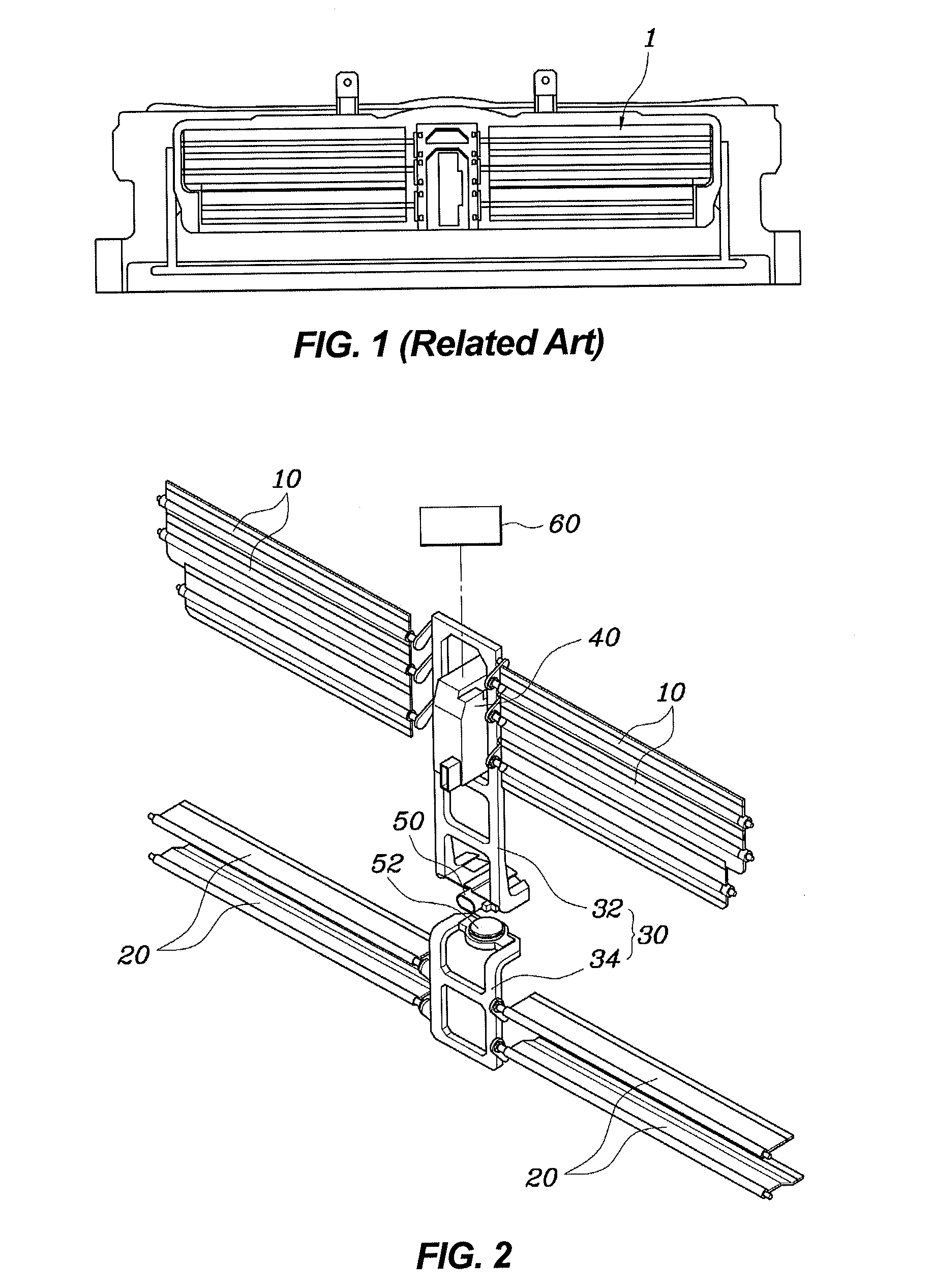
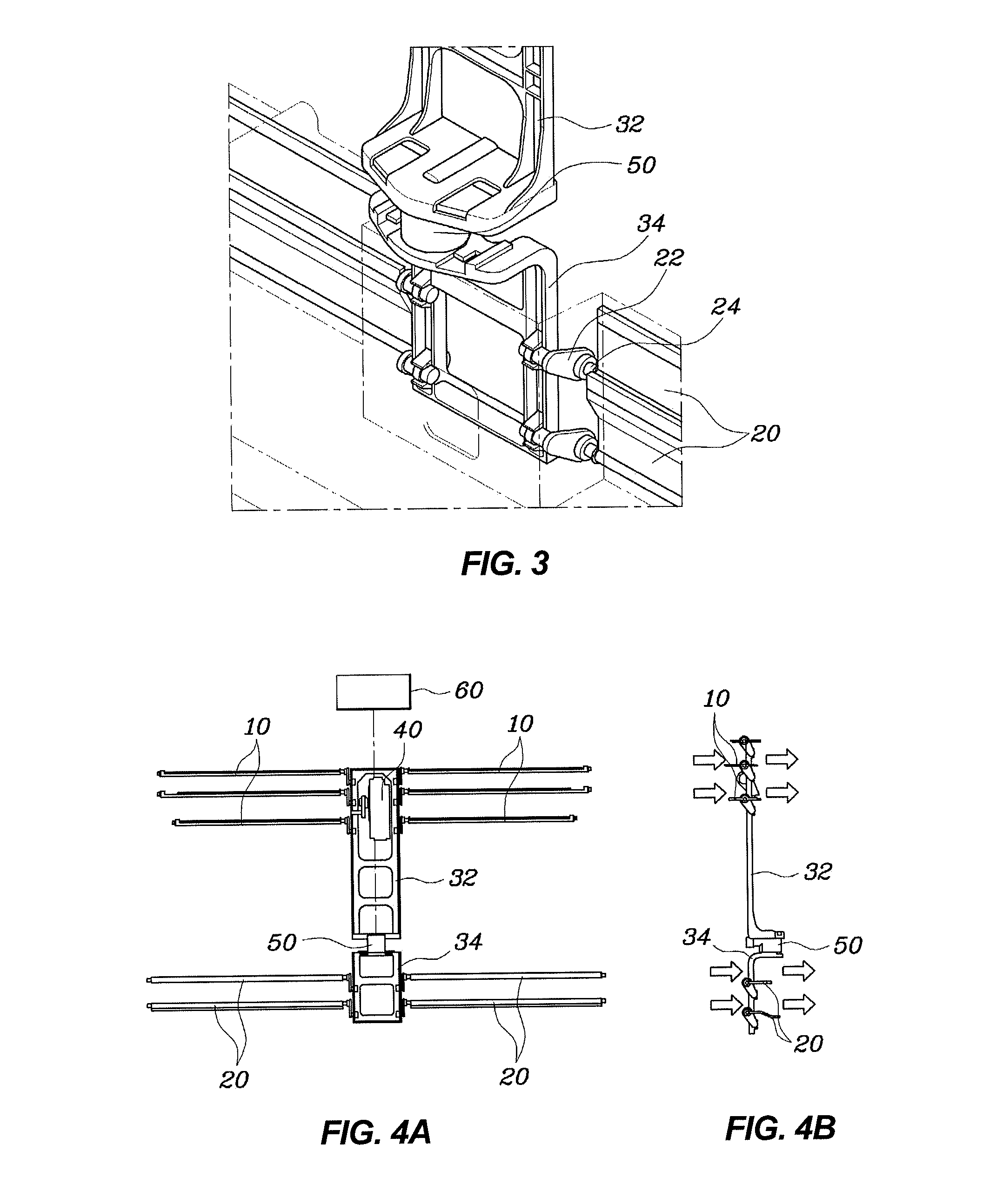
[0031]FIG. 2 is a perspective view illustrating the overall shape of an active air flap device for vehicles according to the present invention. FIG. 3 is an enlarged view illustrating the shape of both a link module and a second flap that are provided in a lower part of the active air flap device according to the present invention.

[00...


PUM


Abstract

An active air flap device for vehicles includes a first flap installed in the front end of a vehicle and is configured such that the first flap is rotated by power of an actuator so as to be opened or closed, a second flap installed at a location around the first flap and configured such that the second flap is rotated so as to be opened or closed, and a link module connected to the first flap at a first end thereof and connected to the second flap at a second end thereof, and configured such that the link module is moved upward and downward, with a regulation unit provided in a central portion of the link module so that the regulation unit can connect or disconnect a link of the first flap to or from a link of the second flap.

Description

CROSS-REFERENCE TO RELATED APPLICATION[0001]The present application claims priority of Korean Patent Application Number 10-2013-0057478 filed May 22, 2013 the entire contents of which application is incorporated herein for all purposes by this reference.BACKGROUND OF INVENTION[0002]1. Field of Invention[0003]The present invention relates, in general, to active air flap devices for vehicles and, more particularly, to an active air flap device for vehicles which can maximize the aerodynamic performance of a vehicle, thereby increasing the mileage of the vehicle, and can provide a fail-safe function to the vehicle, thereby realizing improved driving safety of the vehicle.[0004]2. Description of Related Art[0005]Generally, an air intake unit that is installed in the front end of a vehicle comprises upper and lower parts separated from each other based on a front bumper back beam. In the related art, active air flap devices that are currently used in the air intake units are classified i...

Claims


Application Information

Patent Timeline
Patent Type & Authority Applications(United States)
IPC IPC(8): B62D35/00B60K11/08
CPCB60K11/085B62D35/00Y02T10/88B62D25/08B60K11/08
Inventor LEE, JUNG JOONGLEE, SEUNG HYEOBJEONG, PHIL JUNG
Owner HYUNDAI MOTOR CO LTD
Why Eureka
Try Eureka