
Electrostatic Transformer

Inactive Publication Date: 2014-11-27
AOI ELECTRONICS CO LTD
View PDF4 Cites 4 Cited by
  • Summary
  • Abstract
  • Description
  • Claims
  • Application Information

AI Technical Summary

Benefits of technology

The present invention is related to an electrostatic transformer. The technical effect of this invention is that it provides an electrostatic transformer that can effectively work with a movable electrode that can be easily displaced to adjust its distance from the fixed electrode. This allows for greater flexibility and efficiency in the use of the transformer. Additionally, the electrodes can be designed in different ways to further enhance the performance of the transformer.

Problems solved by technology

However, this type of electrostatic transformer known in the related art is designed on the assumption that it is to be configured with electrostatic comb teeth actuators manufactured by adopting the MEMS technology and the use of such electrostatic comb teeth actuators is bound to lead to more complicated manufacturing processes and an increase in the manufacturing costs.
In addition, it is difficult to manufacture a high-output, low cost electrostatic transformer configured with electrostatic comb teeth actuators manufactured by adopting the MEMS technology.

Method used


Image

  • Electrostatic Transformer
  • Electrostatic Transformer
  • Electrostatic Transformer

Examples


embodiment 1

Variation 4 of Embodiment 1

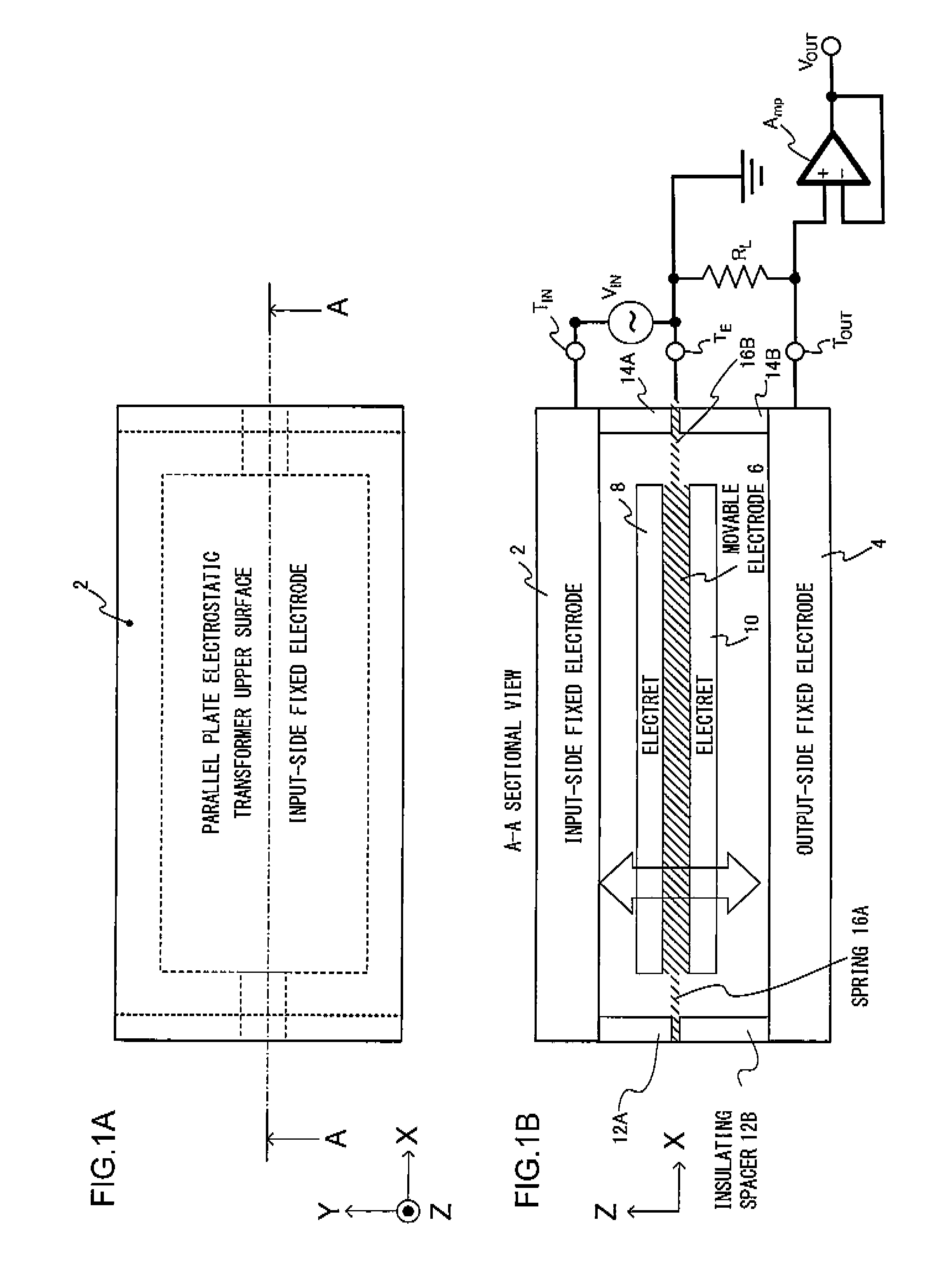
[0054]FIGS. 6A and 6B show an electrostatic transformer achieved as variation 4 of embodiment 1 in a plan view (FIG. 6A) and a sectional view (FIG. 6B). The electrostatic transformer shown in the figures, achieved by modifying the electrostatic transformer described earlier in reference to FIGS. 1A and 1B, includes an internal insulating layer 18 (see FIG. 3B) disposed within the movable electrode so as to allow it to be used in a four-terminal transformer and further includes dielectric layers 50A and 50B each achieving a high dielectric constant, inserted therein so as to increase the electrostatic capacity.

[0055]By inserting the high dielectric constant layers 50A and 50B in the gaps, one present on the side where the input-side electrostatic actuator is located and another present on the side where the output-side electrostatic actuator is located, the electrostatic capacity can be increased as described above. For instance, the presence of dielectric ...

embodiment 2

Variation 1 of Embodiment 2

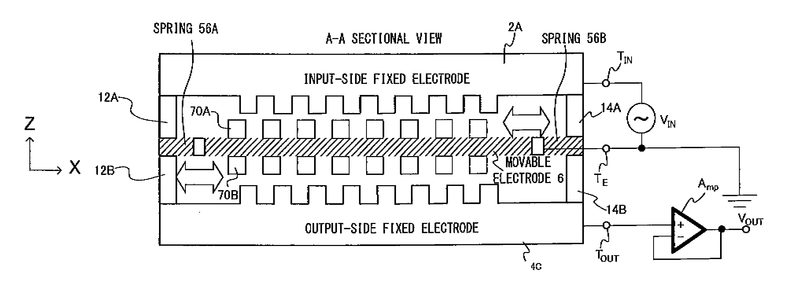
[0064]FIGS. 8A and 8B illustrate variation 1 of embodiment 2. FIG. 8A presents an enlargement of a projecting portion at the output-side fixed electrode 4C in FIG. 7B. Variation 1 of embodiment 2, to be described next, is distinguishable in that a plurality of comb teeth are formed at each projecting portion, as shown in FIG. 8B, at the output-side fixed electrode.

[0065]In variation 1 shown in FIG. 8B, a positional relationship identical to the positional relationship between the movable electrode 30 and the output-side fixed electrode 4B shown in FIG. 5B is adopted. Namely, as the movable electrode 6 shown in FIG. 7B vibrates along the lateral direction (i.e., along the X axis) the electric charge induced at the output-side fixed electrode 4C increases / decreases each time the electrets 70B each pass by a comb tooth portion, which allows the AC output voltage VOUT to assume a frequency higher than the frequency of the AC input voltage VIN. Namely, the elec...

embodiment 3

[0067]FIGS. 9A and 9B show an electrostatic transformer manufactured in embodiment 3, in a plan view (FIG. 9A) and a sectional view (FIG. 9B). The electrostatic transformer to be described next represents a type of electrostatic transformer adopting a structure that allows vibration both along the horizontal direction (i.e., along the X axis) and along the vertical direction. In the electrostatic transformer shown in FIGS. 1A and 1B, for instance, vibration occurs substantially along a single axis, namely in the up / down direction (i.e., along the Z axis), whereas in the electrostatic transformer shown in FIGS. 7A and 7B, vibration occurs only in the left / right direction (i.e., along the X axis). These electrostatic transformers each assume at least one resonance mode and each operate as an electrostatic transformer primarily by using the resonance frequency.

[0068]The electrostatic transformer in this embodiment, on the other hand, assumes two vibration modes, i.e., a vertical direct...


PUM


Abstract

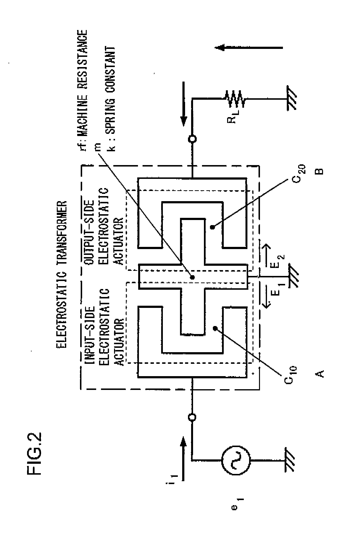
An electrostatic transformer includes: a first fixed electrode; a second fixed electrode; a movable electrode displaceably supported by a flexible member within a space between the first fixed electrode and the second fixed electrode; and permanently charged films disposed on electrode surfaces of the movable electrode. And: an AC output voltage corresponding to a change in an electric charge induced at the second fixed electrode by displacing the movable electrode in response to an AC input voltage applied between the first fixed electrode and the movable electrode is extracted; and a ratio of the AC input voltage and the AC output voltage is determined based upon a ratio of an electromechanical coupling factor at an input-side electrostatic actuator, configured with the first fixed electrode and the movable electrode, and an electromechanical coupling factor at an output-side electrostatic actuator, configured with the second fixed electrode and the movable electrode.

Description

INCORPORATION BY REFERENCE[0001]The disclosure of the following priority application is herein incorporated by reference: Japanese patent application No. 2013-108276 filed May 22, 2013.BACKGROUND OF INVENTION[0002]1. Field of the Invention[0003]The present invention relates to an electrostatic transformer equipped with two sets of electrostatic actuators.[0004]2. Description of Related Art[0005]In an art known in relation to electrostatic transformers, a booster circuit is configured by using a three-terminal comb teeth actuator manufactured through the MEMS technology (see Japanese Laid Open Patent Publication No. 2011-062024). The three-terminal comb teeth actuator described in Japanese Laid Open Patent Publication No. 2011-062024 comprises a first comb teeth actuator that includes a first comb teeth electrode and a second comb teeth electrode engaged with the first comb teeth electrode via a specific gap and a second comb teeth actuator that includes a third comb teeth electrode ...

Claims


Application Information

Patent Timeline
IPC IPC(8): H02N1/08
CPCH02N1/08H02M5/32
Inventor HAYASHI, HIROKISUZUKI, MASATO
Owner AOI ELECTRONICS CO LTD
Learn More