Omni-directional antenna for a cylindrical body

a cylindrical body and omni-directional technology, applied in the direction of resonant antennas, loop antennas with ferromagnetic cores, electrochemical generators, etc., can solve the problems of complex combination, difficult to fabricate, tune, match to rfid/nfc chips,

Active Publication Date: 2014-11-27
DURACELL U S OPERATIONS
View PDF2 Cites 36 Cited by
  • Summary
  • Abstract
  • Description
  • Claims
  • Application Information

AI Technical Summary

Problems solved by technology

Such a combination is difficult to fabricate, tune, and match to the RFID / NFC chip and will most likely require a custom Application Specific Integrated Circuit (ASIC).
Because a typical battery is cylindrical, the combination is further complicated if the antenna is required to be placed on a cylinder.

Method used


Image

  • Omni-directional antenna for a cylindrical body
  • Omni-directional antenna for a cylindrical body
  • Omni-directional antenna for a cylindrical body

Examples


Embodiment Construction

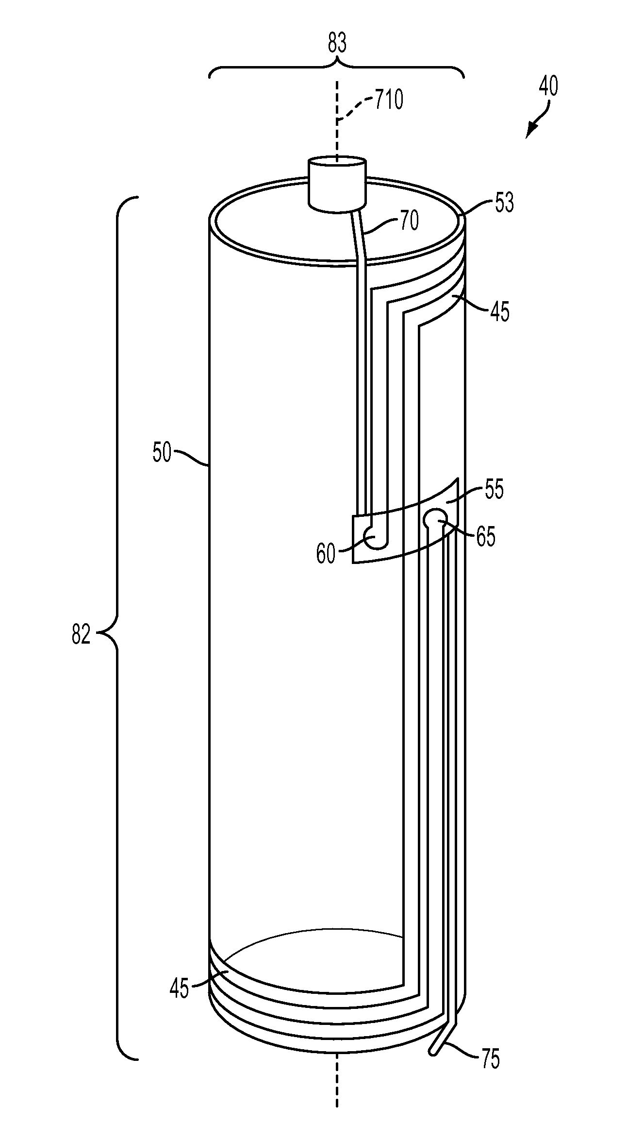
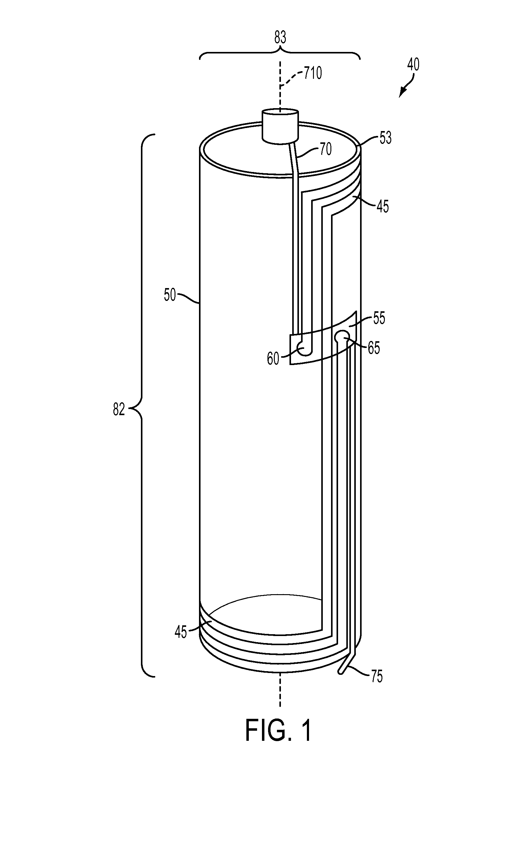
[0020]FIG. 1 generally depicts one embodiment of a single omni-directional antenna that may be placed or printed on a cylindrical body 53 and provide a 3D ability (any orientation of the omni-directional antenna) to be read using RFID / NFC technology. Various embodiments of the omni-directional antenna and the operation of the omni-directional antenna will be described in more detail herein.

[0021]Referring now to FIG. 1, an omni-directional antenna 40 that may be located on a cylindrical body 53 is shown. The omni-directional antenna 40 may include a plurality of antenna traces 45 that may define multiple antennas or define one or more continuous loop antennas. Each loop may have one or more turns or windings of the plurality of antenna traces 45. In one embodiment, the omni-directional antenna 40 is printed directly on the cylindrical body 53. In another embodiment, the omni-directional antenna 40 is printed directly on a flexible substrate 50. The flexible substrate 50 may be, for ...


PUM


Abstract

An antenna for a cylindrical body may include a flexible substrate with the antenna on it with a first terminal and a second terminal electrically connected to an integrated circuit, the flexible substrate coupled to the cylindrical body.

Description

CROSS REFERENCE TO RELATED APPLICATIONS[0001]The present application hereby claims priority under 35 U.S.C. §120 to U.S. application Ser. No. 13 / 901,225 filed May 23, 2013, titled “Omni-Direction Antenna for a Cylindrical Body,” the entirety of which is incorporated by reference herein.FIELD OF THE INVENTION[0002]The present disclosure is generally directed to antenna apparatuses for cylindrical bodies.BACKGROUND OF THE INVENTION[0003]Radio frequency identification (RFID) is gaining in popularity in applications such as security, inventory management, access control, etc. As a sub-category, near field communication (NFC) using the same carrier frequency as RFID in the High-Frequency (HF) range (13.56 MHz) are used in applications such as wireless sensors. The number of NFC-enabled smart phones is growing as well as the various applications of passive or active transponders (RFID tags / NFC tags). Current RFID / NFC loop antennas used in RFID / NFC tags resonate in the 13.56 MHz range and ...

Claims


Application Information

Patent Timeline
Patent Type & Authority Applications(United States)
IPC IPC(8): H01Q1/38H01Q7/00H01Q23/00
CPCH01Q1/38H01Q7/00H01Q23/00H01Q1/20H01Q1/2225H01Q1/225H01M10/48H02J7/00036H02J7/00047Y02E60/10H02J7/005H02J7/0048H01Q7/08H01Q9/26
Inventor BOURILKOV, JORDAN TODOROVCORONADO HORTAL, SERGIOMORRIS, WILLIAM FITLERSPECHT, STEVEN JEFFREYGILES, CALVINSTEFANOV, KONSTANTIN
Owner DURACELL U S OPERATIONS
Why Eureka
Try Eureka