Check patentability & draft patents in minutes with Patsnap Eureka AI!

Overcurrent protection circuit, and electronic control unit

a protection circuit and overcurrent technology, applied in the direction of emergency protection circuit arrangements, emergency protection arrangements for limiting excess voltage/current, etc., can solve the problems of inability to drive an electrical load, difficult to repair a substrate, and inability to recover the fus

Inactive Publication Date: 2014-11-27
TOYOTA JIDOSHA KK
View PDF0 Cites 22 Cited by
  • Summary
  • Abstract
  • Description
  • Claims
  • Application Information

AI Technical Summary

Benefits of technology

The patent is about a circuit that helps protect loads from overcurrent. Its purpose is to protect devices from damage caused by excessive current flow.

Problems solved by technology

However, a fuse cannot recover when once blows out, so a fuse makes it difficult to repair a substrate, or the like.
This inhibits a situation that it is not possible to drive an electrical load in the case where an overcurrent temporarily flows through a load due to noise, or the like.
However, the overcurrent protection circuit described in JP 09-308261 A eventually just turns off the switching element when a load current larger than or equal to a set predetermined current value is detected, and there is an inconvenience that circuit protection may be insufficient.
However, in the thus defined cutoff region, if a load current (5 [A] in the drawing) slightly larger than the nondestructive region continuously flows, it is not possible to cut off the load current.
However, in the thus defined cutoff region, if a load current (40 [A] in the graph) larger than the nondestructive region flows only in a short period of time, it is not possible to cut off the load current.
Thus, when a cutoff region is determined by using a certain set of load current and time as shown in FIG. 2A and FIG. 2B, there is an inconvenience that the circuit may not be protected.

Method used


Image

  • Overcurrent protection circuit, and electronic control unit
  • Overcurrent protection circuit, and electronic control unit
  • Overcurrent protection circuit, and electronic control unit

Examples


Embodiment Construction

[0029]Hereinafter, an embodiment of the invention will be described by way of example embodiments with reference to the accompanying drawings.

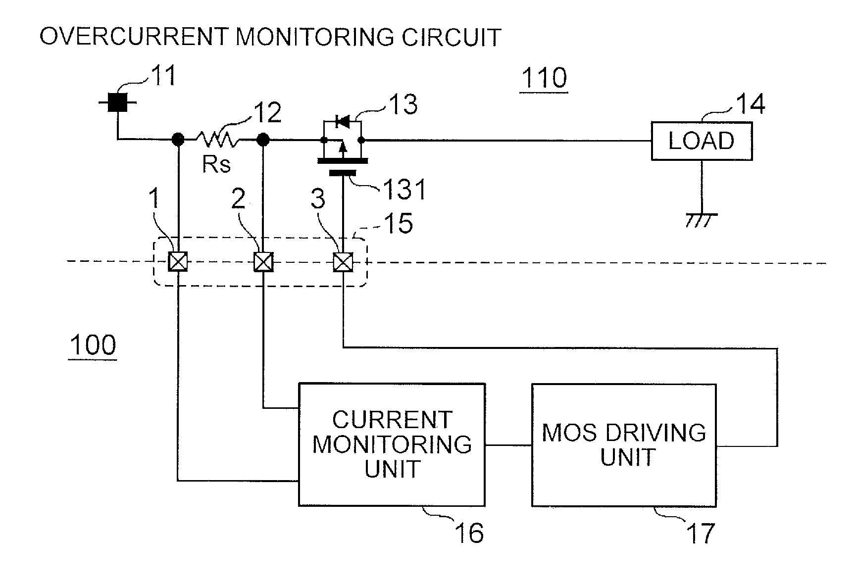
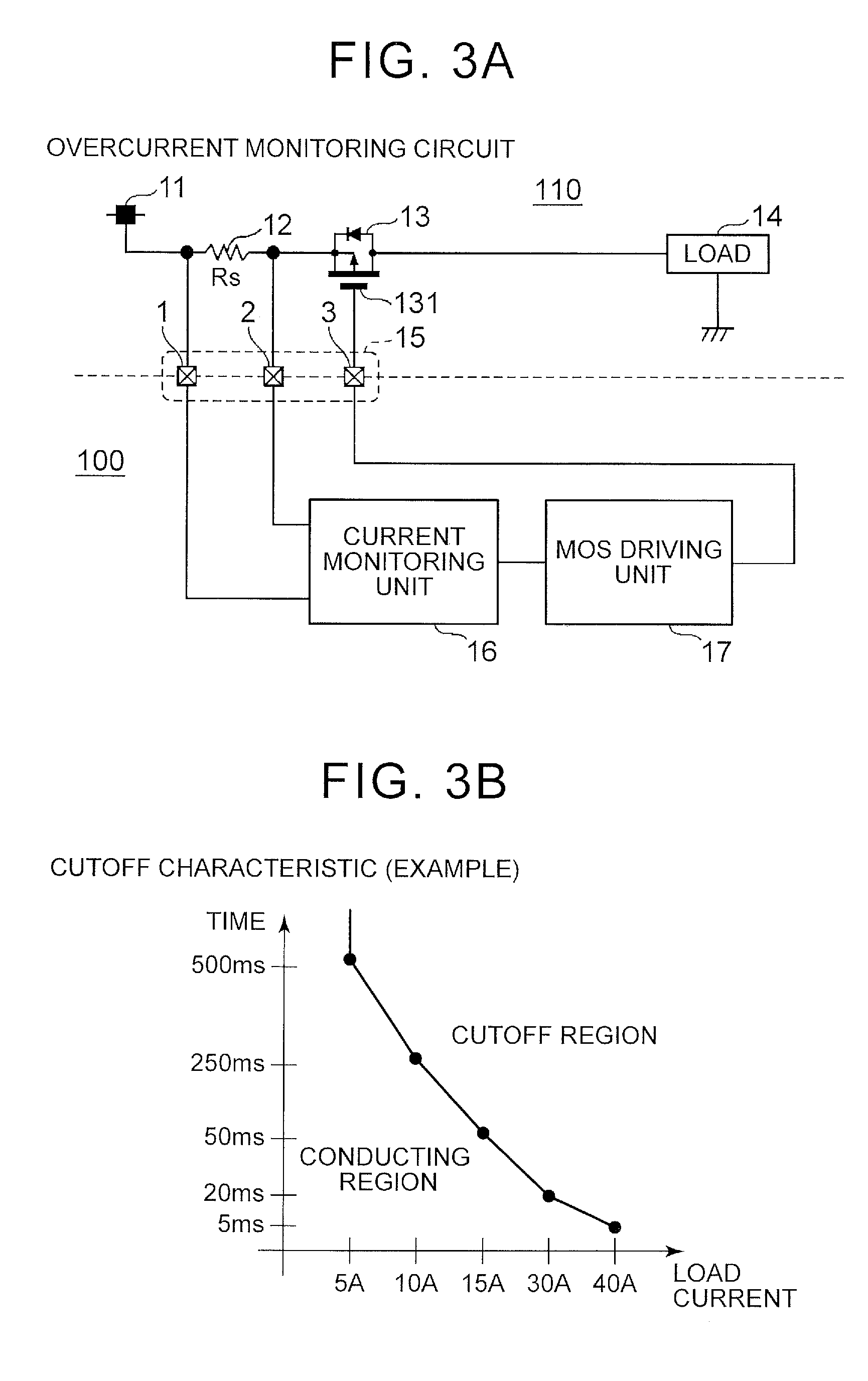
[0030]FIG. 3A and FIG. 3B are examples of views that illustrate an overcurrent protection circuit according to the present embodiment. FIG. 3A shows an example of a circuit configuration. FIG. 3B shows an example of a cutoff characteristic. A monitored circuit 110 and the overcurrent protection circuit 100 are connected to each other by terminals 15. In the monitored circuit 110, a shunt resistor 12 for monitoring a load current and a MOS switch 13 that cuts off the load current are arranged in series with each other between a power supply 11 and a load 14. A current monitoring unit 16 and a MOS driving unit 17 are arranged in the overcurrent protection circuit 100. The current monitoring unit. 16 is connected in parallel with the shunt resistor 12, and the MOS driving unit 17 is connected to the MOS switch 13.

[0031]A plurality of operating po...


PUM


Abstract

An overcurrent protection circuit that protects a load from an overcurrent includes: a load current cutoff condition defining unit configured to set two or more load current cutoff conditions in each of which passage of a load current larger than or equal to a specified current for a specified time or longer is set as a condition for cutting off the load current; a detection unit configured to detect passage of the load current larger than or equal to the specified current for the specified time or longer in at least one of the two or more load current cutoff conditions; and a load current cutoff unit configured to cut off the load current when the detection unit detects that at least one of the load current cutoff conditions is satisfied.

Description

INCORPORATION BY REFERENCE[0001]The disclosure of Japanese Patent Application No. 2013-108252 filed on May 22, 2013 including the specification, drawings and abstract is incorporated herein by reference in its entirety.BACKGROUND OF THE INVENTION[0002]1. Field of the Invention[0003]The invention relates to an overcurrent protection circuit, and the like, that protect a load from an overcurrent.[0004]2. Description of Related Art[0005]The type and number of electrically controlled loads are increasing, and further highly accurate current monitoring is desired. In order to protect various electrical circuits and substrates from a large current larger than or equal to a rated value and prevent overheating, or the like, a fuse (chip fuse) may be arranged. The fuse blows out in a blowout time based on a current value when a current larger than a rated current flows, thus preventing flow of overcurrent.[0006]FIG. 1 is a graph that shows an example of a fuse characteristic. The correlation...

Claims


Application Information

Patent Timeline
IPC IPC(8): H02H9/02
CPCH02H9/025H02H3/0935
Inventor UEHARA, MANABU
Owner TOYOTA JIDOSHA KK
Features
  • R&D
  • Intellectual Property
  • Life Sciences
  • Materials
  • Tech Scout
  • Unparalleled Data Quality
  • Higher Quality Content
  • 60% Fewer Hallucinations
Learn More