

Power supply circuit for gate driving circuit of a power converter
- Summary
- Abstract
- Description
- Claims
- Application Information
AI Technical Summary
Benefits of technology
Problems solved by technology
Method used
Image

Examples
embodiment example 1
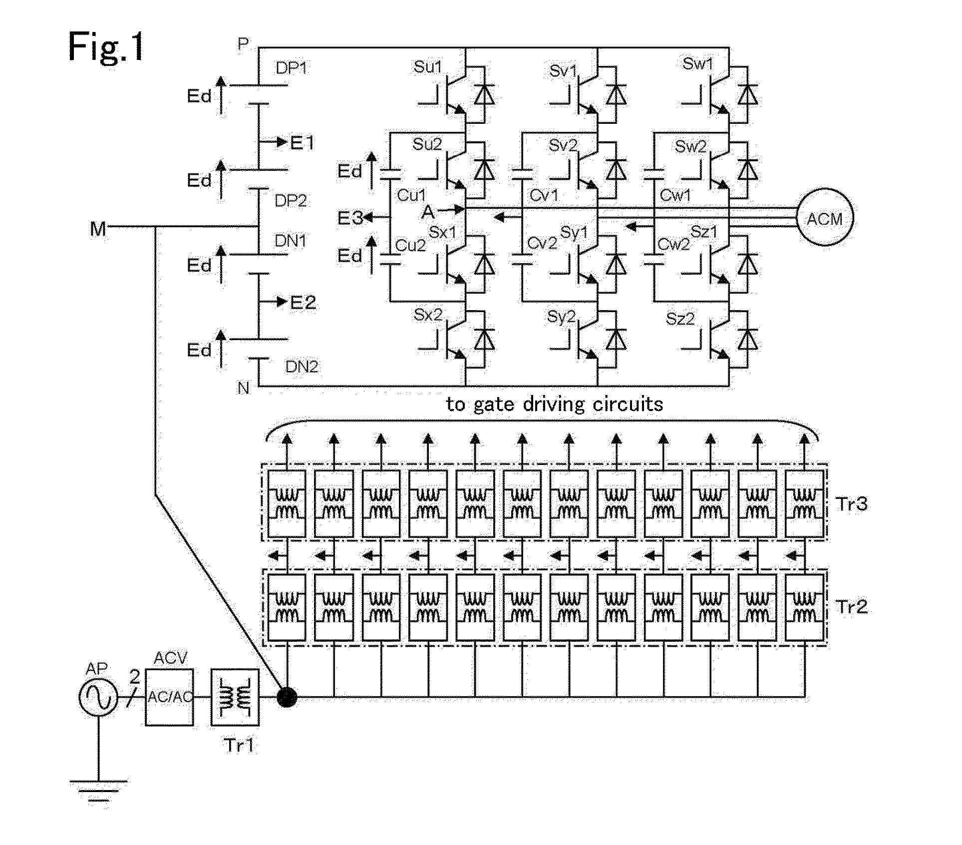
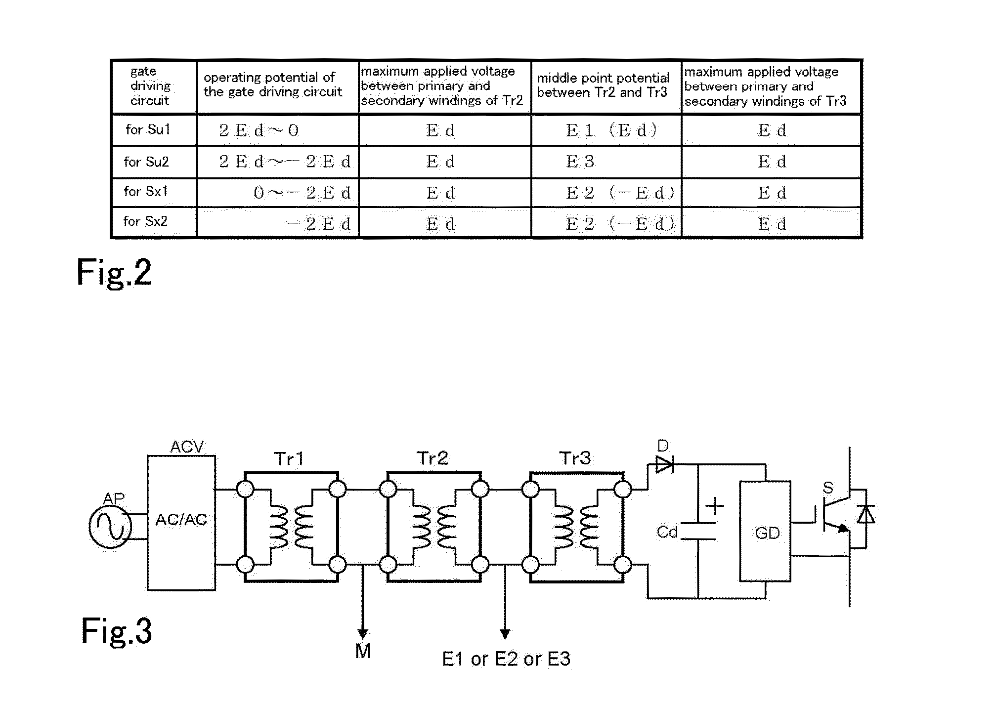
[0032]FIG. 1 shows Embodiment Example 1, which is an embodiment in a three-level three-phase output inverter circuit using a flying capacitor. A gate driving circuit is connected to the gate of each IGBT, which is a semiconductor switching device, although FIG. 1 omits the gate driving circuit. Because the three phases have the same construction, only the U-phase is described in detail in the following. A series circuit of four semiconductor switching devices Su1, Su2, Sx1, and Sx2 is connected between a positive terminal P and a negative terminal N of a DC power supply consisting of DC single power supplies DP1, DP2, DN1, and DN2. A series circuit of flying capacitors Cu1 and Cu2 is connected between the connection point between the semiconductor switching devices Su1 and Su2 and the connection point between the semiconductor switching devices Sx1 and Sx2. When the voltage of the DC power supply is 4Ed, three levels of potential 2Ed, 0, −2Ed can be delivered at the AC output point ...
embodiment example 2
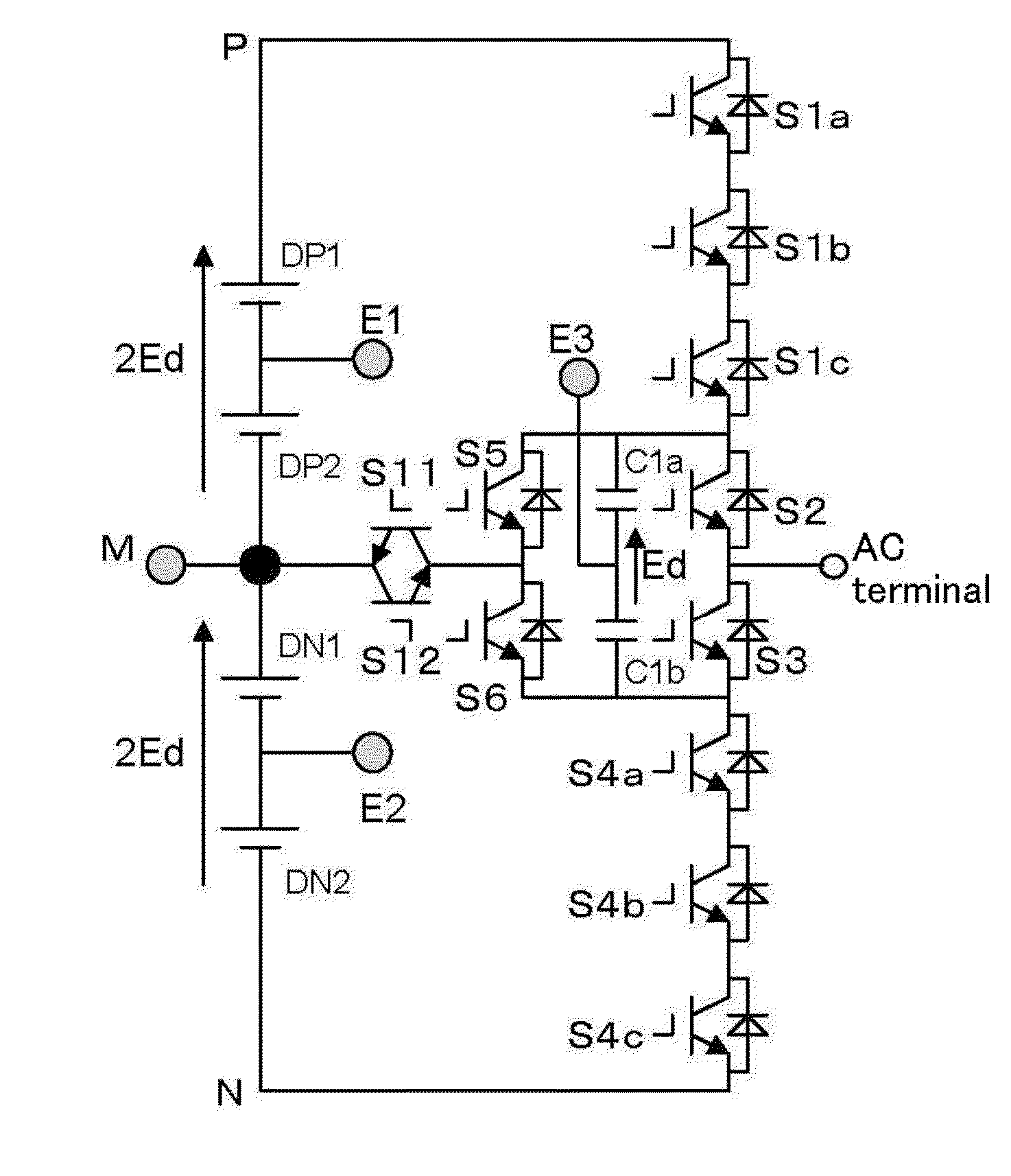
[0036]FIG. 4 shows a power conversion circuit to which Embodiment Example 2 of the present invention is to be applied. The circuit is a flying capacitor type power conversion circuit that can deliver five levels of output voltages. The following describes about only one phase in detail, because the other phases have the same construction. Because a five-level power conversion circuit is disclosed in Japanese Unexamined Patent Application Publication No. 2012-182974, for example, a detailed description is omitted here. The circuit construction for Embodiment Example 2 shown in FIG. 4 differs from the circuit construction of Embodiment Example 1 shown in FIG. 1 in that the circuit of FIG. 4 includes a series circuit of semiconductor switching devices S5 and S6 connected in parallel to the series circuit of the flying capacitors C1a and C1b, and includes a bidirectional switch having antiparallel-connected reverse-blocking IGBTs S11 and S12 between the series connection point between t...
embodiment example 3
[0039]FIG. 6 shows a power conversion circuit to which Embodiment Example 3 of the present invention is to be applied. The circuit is a flying capacitor type power conversion circuit that can deliver seven-levels of output voltages. The following describes about only one phase. A seven-level power conversion circuit was invented by the inventor of the present invention and has been disclosed in Japanese Unexamined Patent Application Publication No. 2013-146117. Therefore, detailed description is omitted here. The main circuit of the circuit of FIG. 6 has a construction expanded from the circuit structure of Embodiment Example 2 of FIG. 4 to perform seven-level operation. The main circuit includes a series circuit of semiconductor switching devices S1a through S1d, S2 through S5, and S6a through S6d, the series circuit being connected in parallel with a DC power supply consisting of DC single power supplies of DP1, DP2, DP3, DN1, DN2, and DN3.
[0040]The circuit of FIG. 6 further inclu...
PUM
 Abstract
Description
Claims
Application Information