Laboratory centrifuge having insulated compressor

a centrifuge and compressor technology, applied in centrifuges and other directions, can solve the problems of shock to the centrifuge, worsening the separation of samples, and affecting so as to prevent vibration transmission, reduce noise disturbance for users, and improve the separation effect of samples.

Active Publication Date: 2014-11-27
THERMO ELECTRONICS LED GMBH
View PDF11 Cites 3 Cited by
  • Summary
  • Abstract
  • Description
  • Claims
  • Application Information

AI Technical Summary

Benefits of technology

[0007]Fundamentally, the damping material can be provided on the entire housing surface of the compressor in addition to the head region. However, it is preferable to only attach the damping material regionally to the compressor housing and to leave it out in the lower two thirds of the compressor housing. It is especially preferable to provide 5% to 50% of the surface of the compressor housing with the damping material. More preferably, the damping material does not cover more than 30% of the compressor housing surface, since in this manner it is ensured particularly well that the compressor can discharge the heat it generates during operation to the outside and thus does not overheat. The size of the surface fraction covered with damping material is thus dependent in particular on which vibrations are to be expected during operation of the compressor, which damping properties the used damping material has, and how much heat the compressor generates during its operation. The stronger the damping properties of the damping material used, the smaller the area will typically be which is to be covered with damping material. The stronger the vibrations generated by the compressor, the more compressor surface must be covered with damping material or the stronger the damping properties the damping material must have.
[0013]The present invention prevents the transmission of vibrations of the compressor to other regions of the centrifuge in a simple manner, in particular to the centrifuge housing and the rotor containing the samples, and thus reduces the noise disturbance for the user. The separation result of the samples can possibly also be improved. The present invention is fundamentally applicable to any type of laboratory centrifuge having a cooling device and a compressor, i.e., for example, in the case of table centrifuges or floor-standing centrifuges.

Problems solved by technology

High temperatures may arise during the operation of the centrifuge, which can have harmful effects on the samples.
In particular if reciprocating piston compressors are used, vibrations are generated, which can result in shocks to the centrifuge and possibly in worsened sample separation.
Above all, the generated vibrations cause an increased noise level, which is perceived to be unpleasant by the users.

Method used


Image

  • Laboratory centrifuge having insulated compressor
  • Laboratory centrifuge having insulated compressor
  • Laboratory centrifuge having insulated compressor

Examples


Embodiment Construction

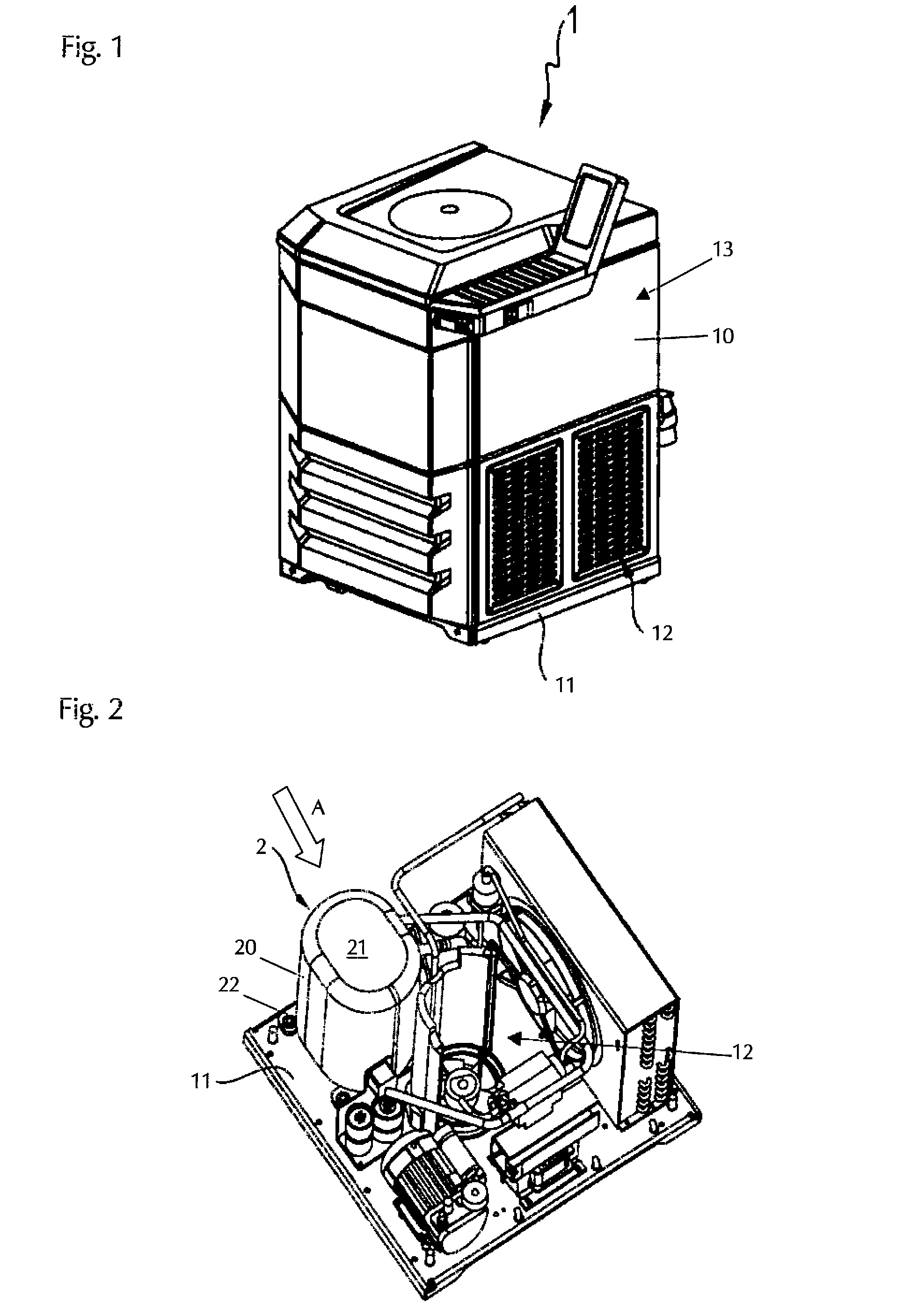
[0019]FIG. 1 shows the view of a laboratory centrifuge 1 according to the present invention on the basis of the example of a floor-standing centrifuge. Except for the damping according to the present invention of the compressor, which is part of the cooling device of the centrifuge 1, the laboratory centrifuge fundamentally corresponds to known prior art centrifuges. A motor and compressor compartment 12 is provided inside the centrifuge housing 10 on the bottom plate 11 and above this, separated from the motor and compressor compartment 12 by an intermediate plate (not visible here), a rotor compartment 13 is provided. The rotor, which is used to accommodate the samples (not visible here), is located in the rotor compartment 13.

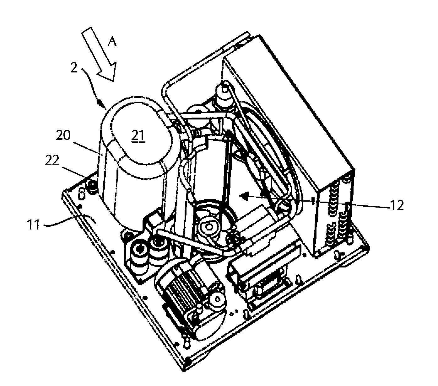
[0020]FIG. 2 shows a top view of the bottom plate 11—i.e., into the motor and compressor compartment 12—with housing 10 removed. In addition to components of the laboratory centrifuge such as, for example, a motor, fan, etc., which are known per se and are n...


PUM


Abstract

The present invention relates to a laboratory centrifuge having a cooling device which comprises a compressor enclosed by a compressor housing, with the compressor housing, in the region of the compressor head, being at least regionally provided with a damping material which is capable of absorbing vibrations in the range from 20 Hz to 100 Hz.

Description

CROSS-REFERENCE TO RELATED APPLICATIONS[0001]The present application claims priority under 35 U.S.C. §119 of German Patent Application Nos. 20 2013 004 850.6, filed May 27, 2013, and 20 2013 009 485.0, filed Oct. 25, 2013, the disclosures of which are hereby incorporated herein by reference in their entireties.FIELD OF THE INVENTION[0002]The present invention relates to a laboratory centrifuge having a cooling device which comprises a compressor enclosed by a compressor housing.BACKGROUND OF THE INVENTION[0003]Such laboratory centrifuges are used in chemical, biological, biochemical, or medical laboratories for separating samples which contain substances of different masses. In particular, laboratory centrifuges are used to separate solids from liquids with the aid of the centrifugal force generated during the rotation procedure. High rotational velocities of 20,000 RPM or more are frequently necessary for this purpose. High temperatures may arise during the operation of the centrif...

Claims


Application Information

Patent Timeline
Patent Type & Authority Applications(United States)
IPC IPC(8): B04B15/02
CPCB04B15/02B04B7/02
Inventor JANZEN, HANS
Owner THERMO ELECTRONICS LED GMBH
Why Eureka
Try Eureka