Linear drive system for hair clippers

Active Publication Date: 2014-12-04
WAHL CLIPPER
View PDF4 Cites 4 Cited by
  • Summary
  • Abstract
  • Description
  • Claims
  • Application Information

AI Technical Summary

Benefits of technology

[0008]In keeping with one aspect of this invention, a hair clipper has a base housing and a secondary housing cover. A motor is secured between the base housing and the secondary housing cover. The motor can be a rotary motor having a shaft, a cam secured to an end of the shaft and a cam shaft, or a vibrator motor with a drive finger.
[0009]A cam follower is operably

Problems solved by technology

They may use a spring to guide the reciprocating blade in a near-linear path, but spring tolerances are difficult to sustain in manufacturing.
Some drive systems have a guide channel formed in a thick section of the stationary blade, but the thick section is distanced from the cutting load, making the reciprocating blade guiding susceptible to binding.
Moreover, sometimes an external feature (such as a cam follower flange) recipr

Method used


Image

  • Linear drive system for hair clippers
  • Linear drive system for hair clippers
  • Linear drive system for hair clippers

Examples


Embodiment Construction

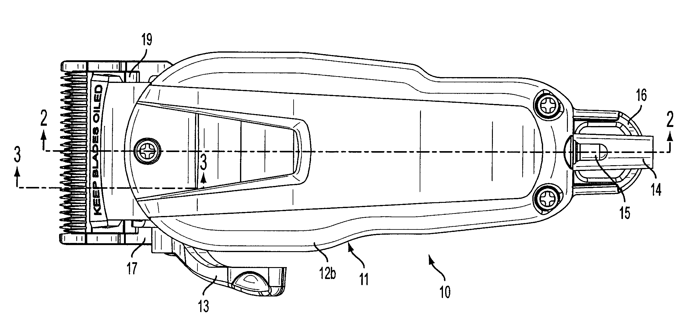
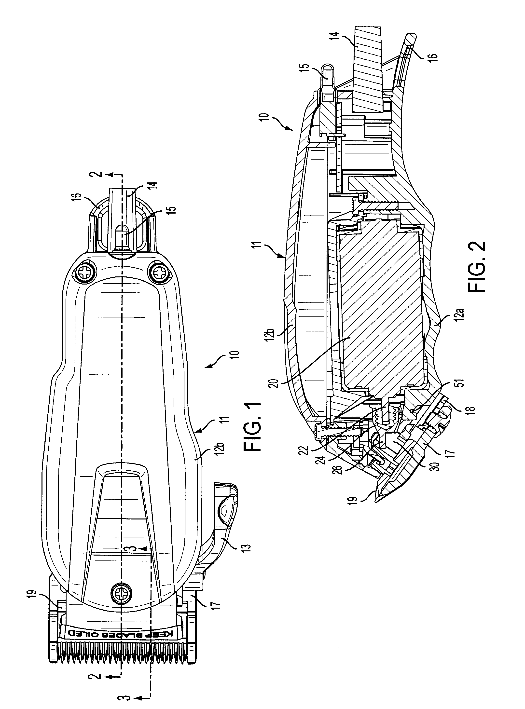
[0027]Referring to FIGS. 1 to 5, a hair clipper 10 (also known as a hair trimmer) has a housing 11. The housing 11 includes a base housing 12a and a secondary housing cover 12b. A taper adjustment lever 13, a power cord 14, a switch 15 and a hook hanger 16 are also provided.

[0028]A stationary blade 17 is secured to a taper adjustment bar 18, which in turn is slidably secured to the base housing 12a. The taper adjustment bar 18 and taper adjustment lever 13 are optional. The stationary blade 17 is operably secured to the base housing 12a, with or without blade adjustment.

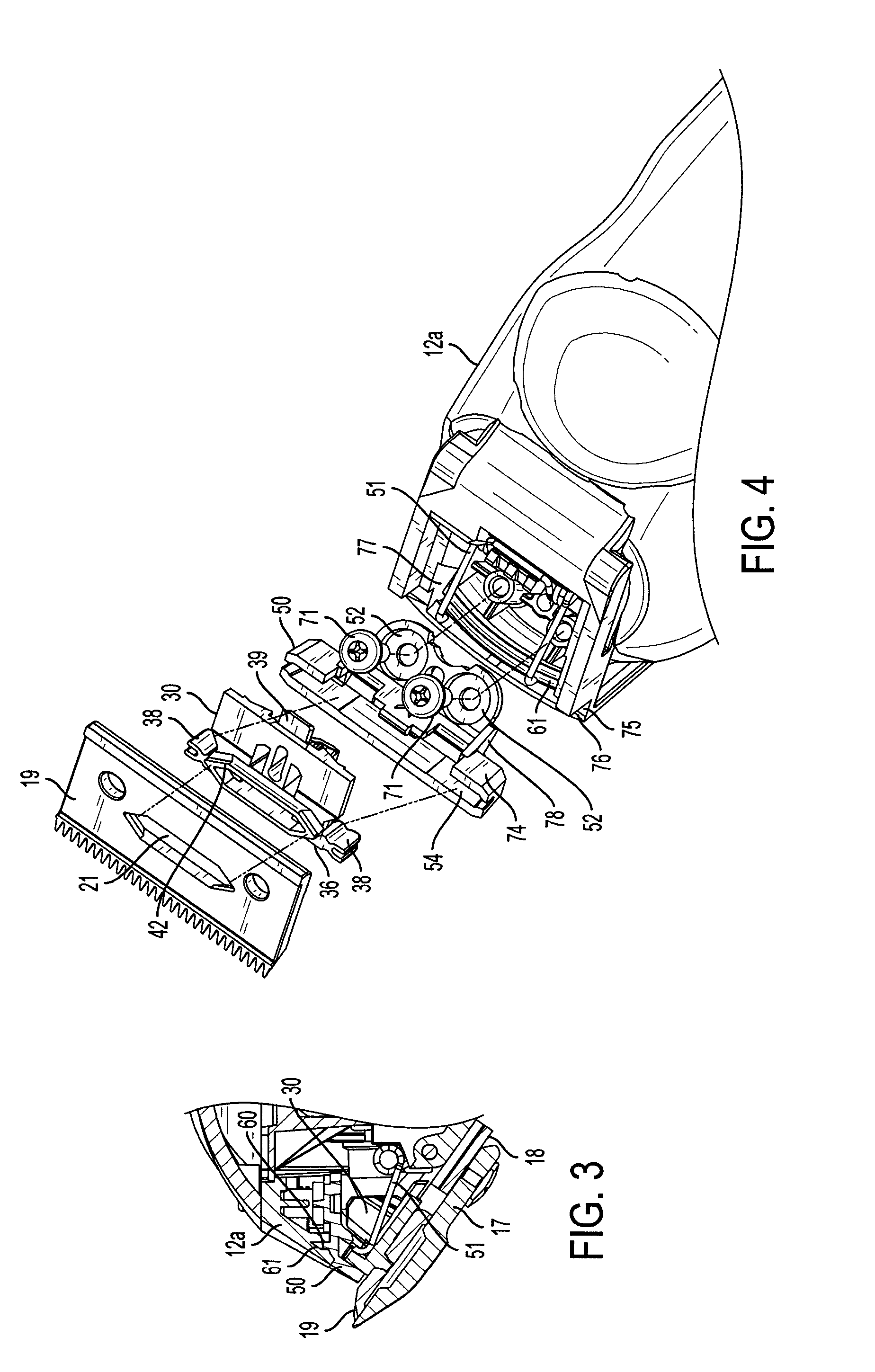
[0029]A reciprocating blade 19 is operably secured adjacent the stationary blade 17. As seen in FIG. 4 and FIG. 5, the reciprocating blade 19 has an opening 21.

[0030]In this embodiment, a rotary motor 20 (FIG. 2) is secured between the base housing 12a and the secondary housing cover 12b. The motor 20 has a shaft 22 and a cam 24 secured to an end of the shaft 22.

[0031]The cam 24 has an off-center (i.e., eccentric) ca...


PUM


Abstract

A hair clipper has a base housing, a secondary housing cover, and a rotary motor or vibrator motor secured between the base housing and the housing cover. The rotary motor has a shaft and a cam secured to an end of the shaft, and the vibrator motor has a drive arm with a drive finger. A cam follower is operably connected to the cam or drive finger on a top side. The top side of the cam follower also has an elongated guide rail that is operably secured to a guide channel in a blade guide, which in turn is secured to the base housing. A reciprocating blade is operably secured to the bottom side of the cam follower, and a stationary blade is secured to the base housing adjacent the reciprocating blade.

Description

[0001]This invention relates to hair clippers, and more particularly to drive systems for hair clippers driven by a rotary motor or a vibrator motor.BACKGROUND OF THE INVENTION[0002]Hair clippers require drive systems that maintain linear motion of a reciprocating blade. To guide the reciprocating blade parallel to the stationary blade, the drive systems require precision tolerances. They may use a spring to guide the reciprocating blade in a near-linear path, but spring tolerances are difficult to sustain in manufacturing. As a result, the spring often requires adjustment at the factory assembly line to properly align the reciprocating blade with respect to the stationary blade.[0003]Some drive systems have a guide channel formed in a thick section of the stationary blade, but the thick section is distanced from the cutting load, making the reciprocating blade guiding susceptible to binding. Moreover, sometimes an external feature (such as a cam follower flange) reciprocates outsid...

Claims


Application Information

Patent Timeline
IPC IPC(8): B26B19/06
CPCB26B19/06B26B19/28
Inventor ARNDT, STEVENSNOW, GARYGESIAKOWSKI, JEFFBUCK, JR., ROBERT
Owner WAHL CLIPPER
Why Eureka
Try Eureka