Method for collecting condensate inside an apparatus, apparatus equipped with a condensate collection system and motor-pump assembly intended for a condensate collection system

Active Publication Date: 2014-12-04
ASKOLL HLDG S R L A SOCIO UNICO
View PDF3 Cites 4 Cited by
  • Summary
  • Abstract
  • Description
  • Claims
  • Application Information

AI Technical Summary

Benefits of technology

[0040]The effect of the first parameter can be partly compensated for by adopting a variable threshold, depending on the instantaneous grid voltage; this however increases the computational complexity o

Problems solved by technology

In fact, in the event of the collection system being completely full, continuous recirculation of the condensed liquid between the bottom t

Method used


Image

  • Method for collecting condensate inside an apparatus, apparatus equipped with a condensate collection system and motor-pump assembly intended for a condensate collection system
  • Method for collecting condensate inside an apparatus, apparatus equipped with a condensate collection system and motor-pump assembly intended for a condensate collection system
  • Method for collecting condensate inside an apparatus, apparatus equipped with a condensate collection system and motor-pump assembly intended for a condensate collection system

Examples


first embodiment

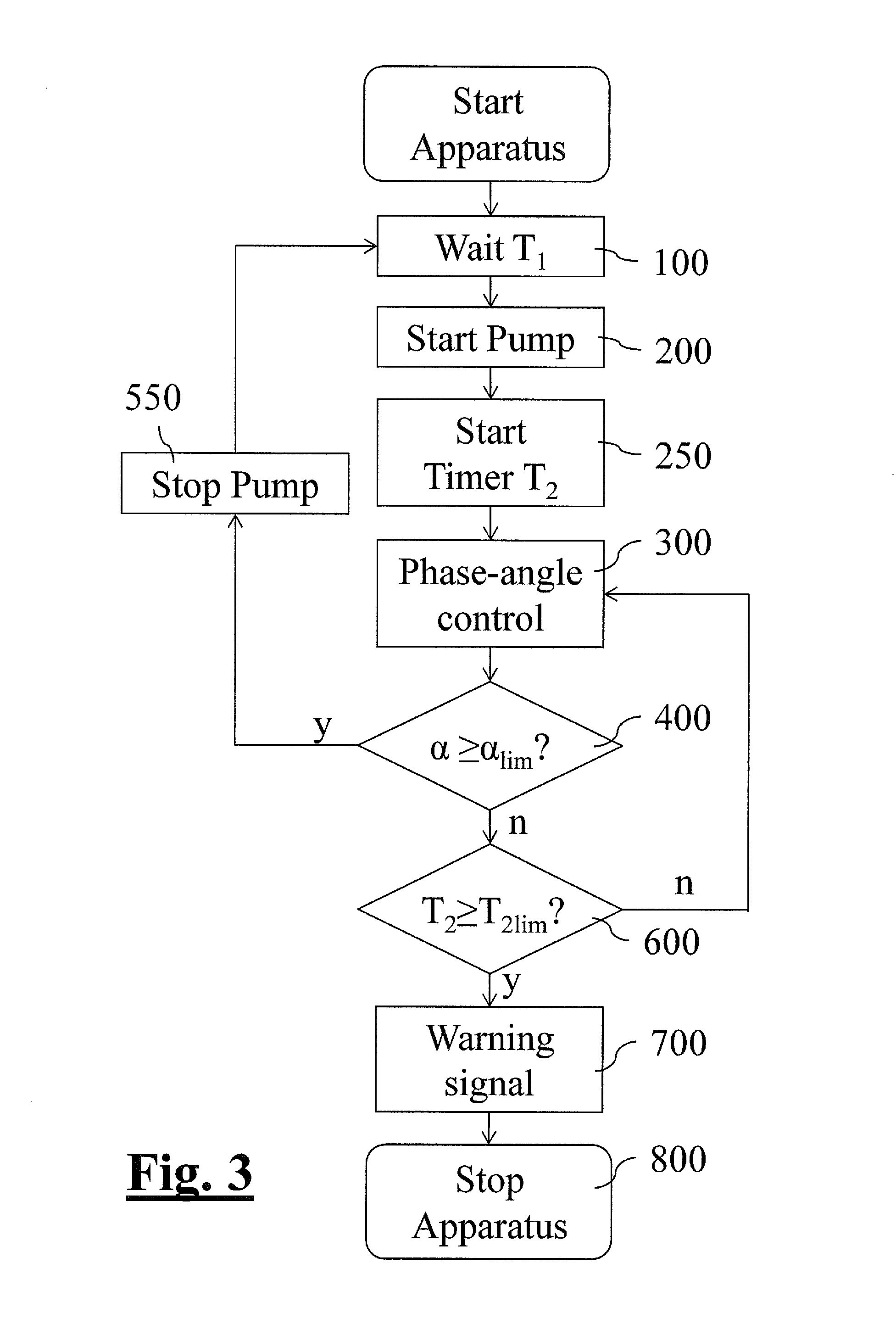
[0082]With reference to the attached FIG. 3, a method of operation, according to the present invention, of the condensate collection system described above is now described.

[0083]This method preferably envisages a cyclical actuation of the condensate discharge pump 50 during operation of the laundry-drying machine 500. Then a waiting step 100 is involves to allow a wait time T1 to elapse between one actuating operation of the condensate discharge pump 50 and the next. This wait time T1 is determined on the basis of the estimated filling time for the bottom collection tank 2.

[0084]It should be noted that cyclical actuation of the condensate discharge pump 50 is not necessarily envisaged for the entire period of operation of the laundry drying machine, but concerns only a number of operating cycles during which condensation is produced inside the machine.

[0085]In the example embodiment described here, the wait time T1 may be between 100 s and 160 s.

[0086]Once said wait time has elapse...

second embodiment

[0126]With reference to the attached FIGS. 6 and 7, a method of operation, according to the present invention, of the condensate collection system described above is now described.

[0127]As may be easily inferred by comparing FIGS. 3 and 6, the second embodiment differs from the first embodiment only in that an alternative method for detecting a partial load condition is applied (compare check step 400 in FIG. 3 and check step 400′ in FIG. 6). Said alternative sub-method 400′ for detecting a partial load condition is depicted in detail in FIG. 7.

[0128]During steady-state driving, the method checks that the synchronous motor 1 has not reached a low load condition which indicates emptying of the bottom collection tank 2.

[0129]When the bottom collection tank 2 no longer contains condensation liquid or contains a minimum amount thereof, the condensate discharge pump 50 operates under zero load or in air / water conditions, with a consequent reduction in load compared to full flow operating...


PUM


Abstract

A method for collecting condensate inside an apparatus, including: providing a condensate collection system with bottom and top collection tanks; a condensate discharge pump to displace liquid from the bottom collection tank to the top collection tank; and an overflow system which displaces the liquid contained in the top collection tank that exceeds an overflow level into the bottom collection tank; collecting a condensed liquid in the bottom collection tank; actuating the condensate discharge pump to displace the condensed liquid from the bottom collection tank into the top collection tank; detecting a low load condition of the condensate discharge pump, actuation of the condensate discharge pump being interrupted upon detection of the low load condition; the actuating time (T2) of the condensate discharge pump, with signalling of a full condition of the condensate collection system when this actuating time (T2) is equal or larger than a maximum time (T2lim).

Description

CROSS-REFERENCE TO RELATED APPLICATIONS[0001]The present application claims priority to European Patent Application No. 13425078.6, filed May 28, 2013 and European Patent Application No, 14425006.5, filed Jan. 29, 2014, the entirety of which are incorporated herein by reference.FIELD OF APPLICATION[0002]The present invention relates, in its most general aspect, to a method for collecting condensate inside an apparatus equipped with a condensate collection system, for example a tumble dryer or an air conditioner.[0003]The present invention also relates to an apparatus equipped with a condensate collection system and to a motor-pump assembly specifically intended to operate a condensate collection system inside an apparatus of the above-mentioned type.[0004]As mentioned above, the invention is intended therefore for the sector of laundry washing or washing / drying machines, or for the sector of air conditioners, in particular portable air conditioners equipped with an internal condensa...

Claims


Application Information

Patent Timeline
IPC IPC(8): F26B21/08F04D15/02F25D21/14
CPCF26B21/086F04D15/0218F25D21/14D06F25/00D06F58/24D06F58/32D06F2103/38D06F2103/44D06F2103/58D06F2105/36D06F2105/62F04B49/06F24F13/222
Inventor MARIONI, ELIO
Owner ASKOLL HLDG S R L A SOCIO UNICO
Why Eureka
Try Eureka