System and method for operating an engine

a technology of internal combustion engine and system, which is applied in the direction of machine/engine, charge feed system, non-fuel substance addition to fuel, etc., can solve the problems of increasing engine noise, increasing engine vibration, and taking many engine cycles to clear the cooled egr from the engine, so as to improve engine efficiency, reduce engine emissions, and improve engine operation

Inactive Publication Date: 2014-12-04
FORD GLOBAL TECH LLC
View PDF4 Cites 12 Cited by
  • Summary
  • Abstract
  • Description
  • Claims
  • Application Information

AI Technical Summary

Benefits of technology

[0002]An engine system may include exhaust gas recirculation (EGR) to improve engine operation. For example, EGR may reduce engine emissions (e.g., NOx) and improve engine efficiency via reducing engine pumping work. In some examples, external EGR (e.g., EGR routed between an exhaust system and an engine air intake system) may be cooled to further reduce engine NOx and reduce the possibility of engine knock at higher engine loads. Cooling the EGR further lowers cylinder charge temperatures, thereby reducing formation of NOx and auto-ignition of end gases. However, at lower engine loads, cooled EGR may cause combustion stability to degrade and lead to the possibility of misfire, increased engine noise, and increased engine vibration. Thus, it may be desirable to use cooled EGR at middle and higher engine loads and reducing its use at lower engine loads. However, since cooled EGR is supplied to the engine intake system, it may take many engine cycles to clear the cooled EGR from the engine intake system when the engine transitions from higher load conditions to lower load conditions. Consequently, engine emissions and combustion stability may degrade when the engine changes from an operating condition where a higher concentration of cooled EGR is supplied to engine cylinders to a condition where a lower concentration of cooled EGR is supplied to engine cylinders.

Problems solved by technology

However, at lower engine loads, cooled EGR may cause combustion stability to degrade and lead to the possibility of misfire, increased engine noise, and increased engine vibration.
However, since cooled EGR is supplied to the engine intake system, it may take many engine cycles to clear the cooled EGR from the engine intake system when the engine transitions from higher load conditions to lower load conditions.
Consequently, engine emissions and combustion stability may degrade when the engine changes from an operating condition where a higher concentration of cooled EGR is supplied to engine cylinders to a condition where a lower concentration of cooled EGR is supplied to engine cylinders.
For example, the approach may reduce the possibility of engine misfires when operating an engine with cooled EGR.

Method used


Image

  • System and method for operating an engine
  • System and method for operating an engine
  • System and method for operating an engine

Examples


Embodiment Construction

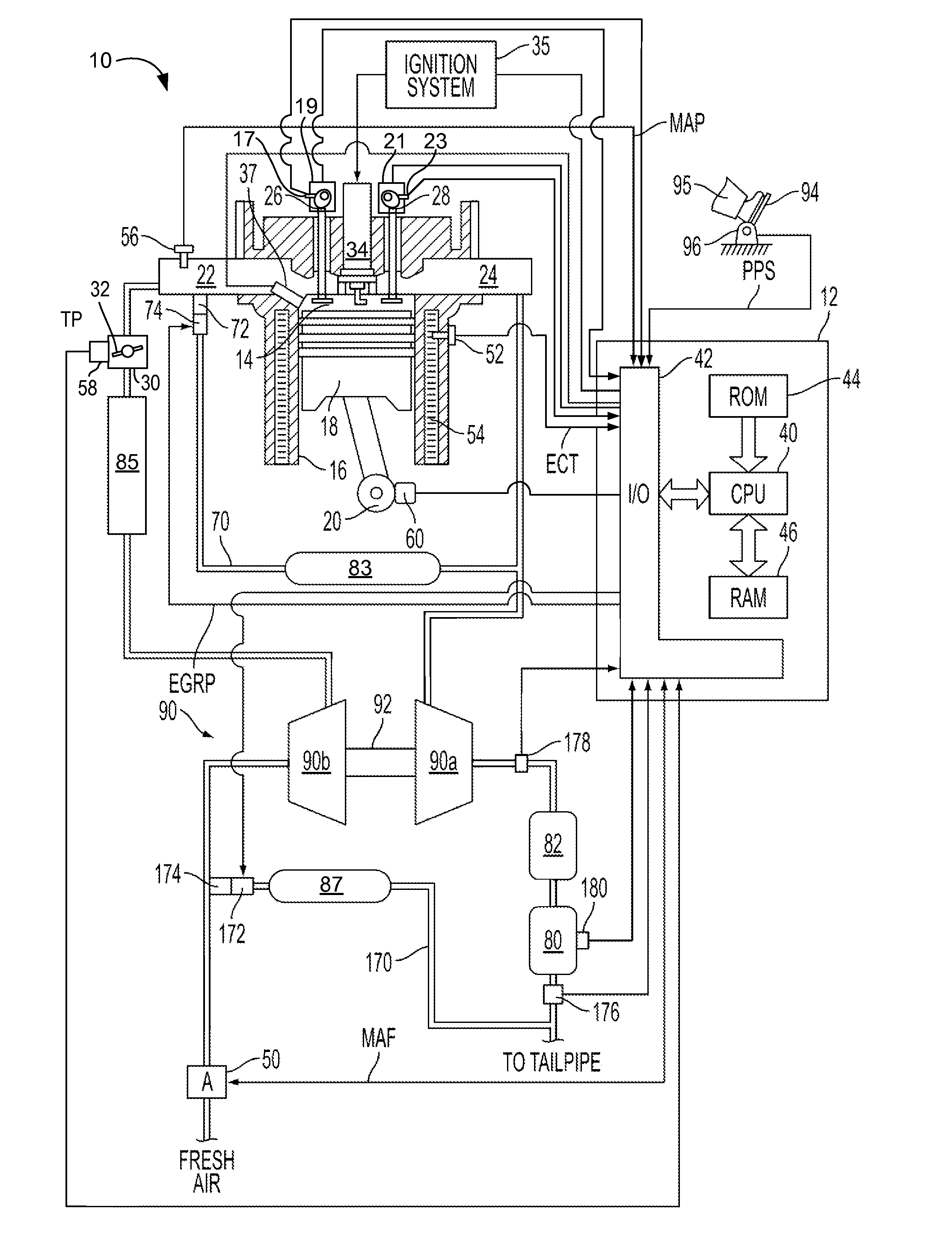
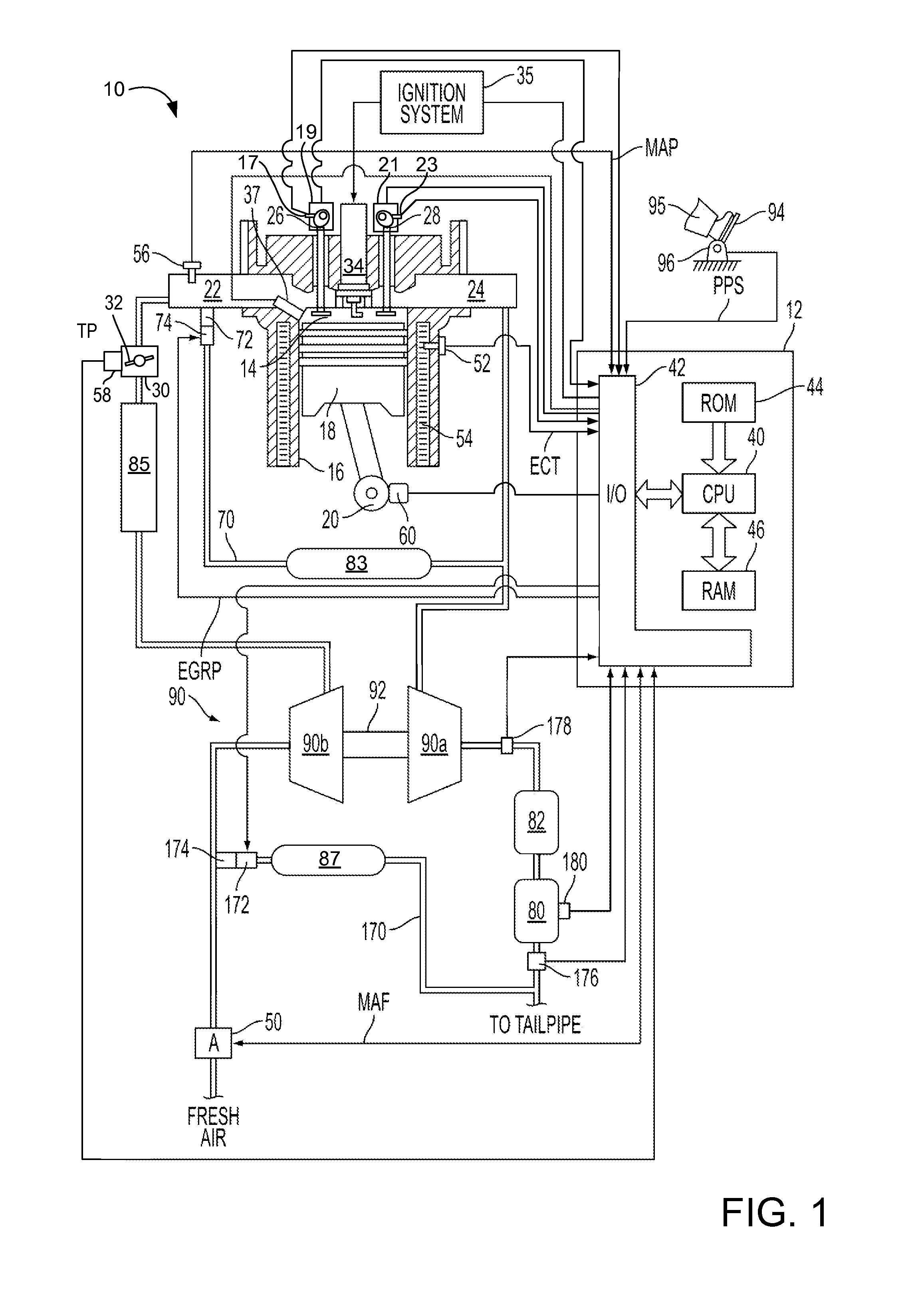
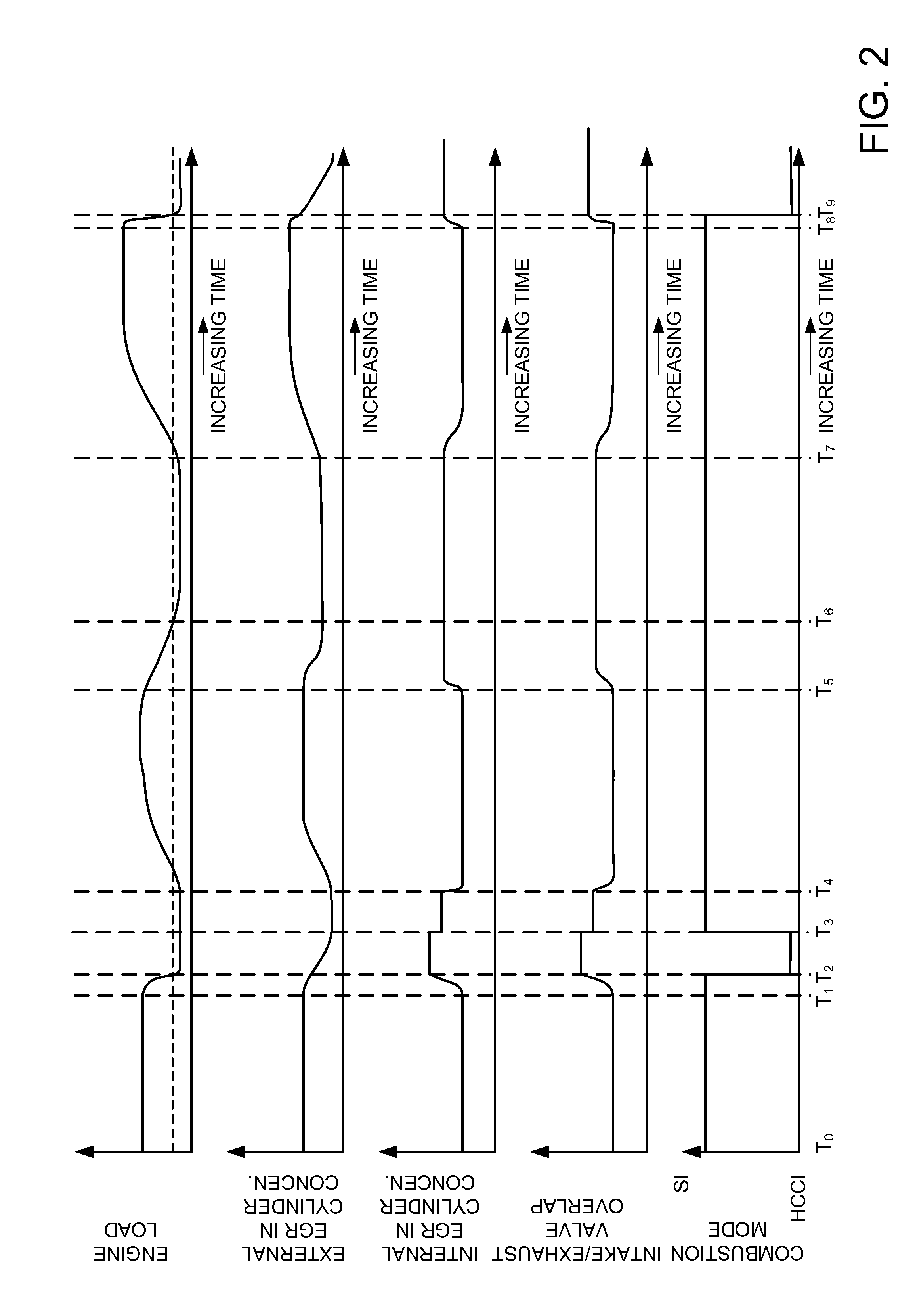
[0011]The present description is related to transitioning an engine between engine loads. FIG. 1 shows one example system providing power to propel a vehicle. The system includes an engine that may operate at lower or higher engine loads depending on a driver demand torque or desired engine torque. The system includes a controller having non-transitory instructions for operating the engine in spark ignition or homogeneous charge compression ignition combustion modes. FIG. 2 shows example engine operating sequence where engine combustion modes are changed to reduce the concentration of cooled external EGR in engine cylinders so that combustion stability may be improved. FIG. 3 is a flowchart of an example method for transitioning the engine in FIG. 1 between spark ignition and homogeneous charge compression ignition combustion modes.

[0012]FIG. 1 shows an example of a gasoline direct injection engine system generally at 10. Specifically, internal combustion engine 10 comprises a plura...


PUM


Abstract

A method for operating an engine is disclosed. In one example, internal EGR is increased during conditions where cooled EGR is at a higher concentration during a decreasing engine load so that homogeneous compression ignition may be initiated at lower engine loads.

Description

TECHNICAL FIELD[0001]The present application relates to the field of internal combustion engines. In particular, the field of operating an internal combustion engine and transitioning the engine from higher engine load conditions to lower engine load conditions.BACKGROUND AND SUMMARY[0002]An engine system may include exhaust gas recirculation (EGR) to improve engine operation. For example, EGR may reduce engine emissions (e.g., NOx) and improve engine efficiency via reducing engine pumping work. In some examples, external EGR (e.g., EGR routed between an exhaust system and an engine air intake system) may be cooled to further reduce engine NOx and reduce the possibility of engine knock at higher engine loads. Cooling the EGR further lowers cylinder charge temperatures, thereby reducing formation of NOx and auto-ignition of end gases. However, at lower engine loads, cooled EGR may cause combustion stability to degrade and lead to the possibility of misfire, increased engine noise, an...

Claims


Application Information

Patent Timeline
Patent Type & Authority Applications(United States)
IPC IPC(8): F02M25/07
CPCF02M25/07F02M26/05F02M26/06
Inventor SURNILLA, GOPICHANDRACURTIS, ERIC WARRENSTYLES, DANIEL JOSEPHMAKKAPATI, SATHEESH
Owner FORD GLOBAL TECH LLC
Why Eureka
Try Eureka