Shell structure for handheld device

a handheld device and shell technology, applied in the field of shell structures, can solve the problems achieve the effects of saving limited space, accelerating heat transfer, and large area

Inactive Publication Date: 2014-12-04
COOLER MASTER DEVELOPMENT CORP
View PDF13 Cites 33 Cited by
  • Summary
  • Abstract
  • Description
  • Claims
  • Application Information

AI Technical Summary

Benefits of technology

[0008]The shell structure of the instant disclosure is entirely or partially formed with a vapor chamber. The recessing face of the vapor chamber contacts those heat generating components in the handheld device and absorbs the heat. The heat is then dissipated to the ambient via the shell structure. The shell structure needs not to be installed inside the handheld device and therefore saves the limited space there-within. The shell structure also has larger area for heat dissipation that accelerates heat transferring.

Problems solved by technology

The shell structure needs not to be installed inside the handheld device and therefore saves the limited space there-within.

Method used


Image

  • Shell structure for handheld device
  • Shell structure for handheld device
  • Shell structure for handheld device

Examples


first embodiment

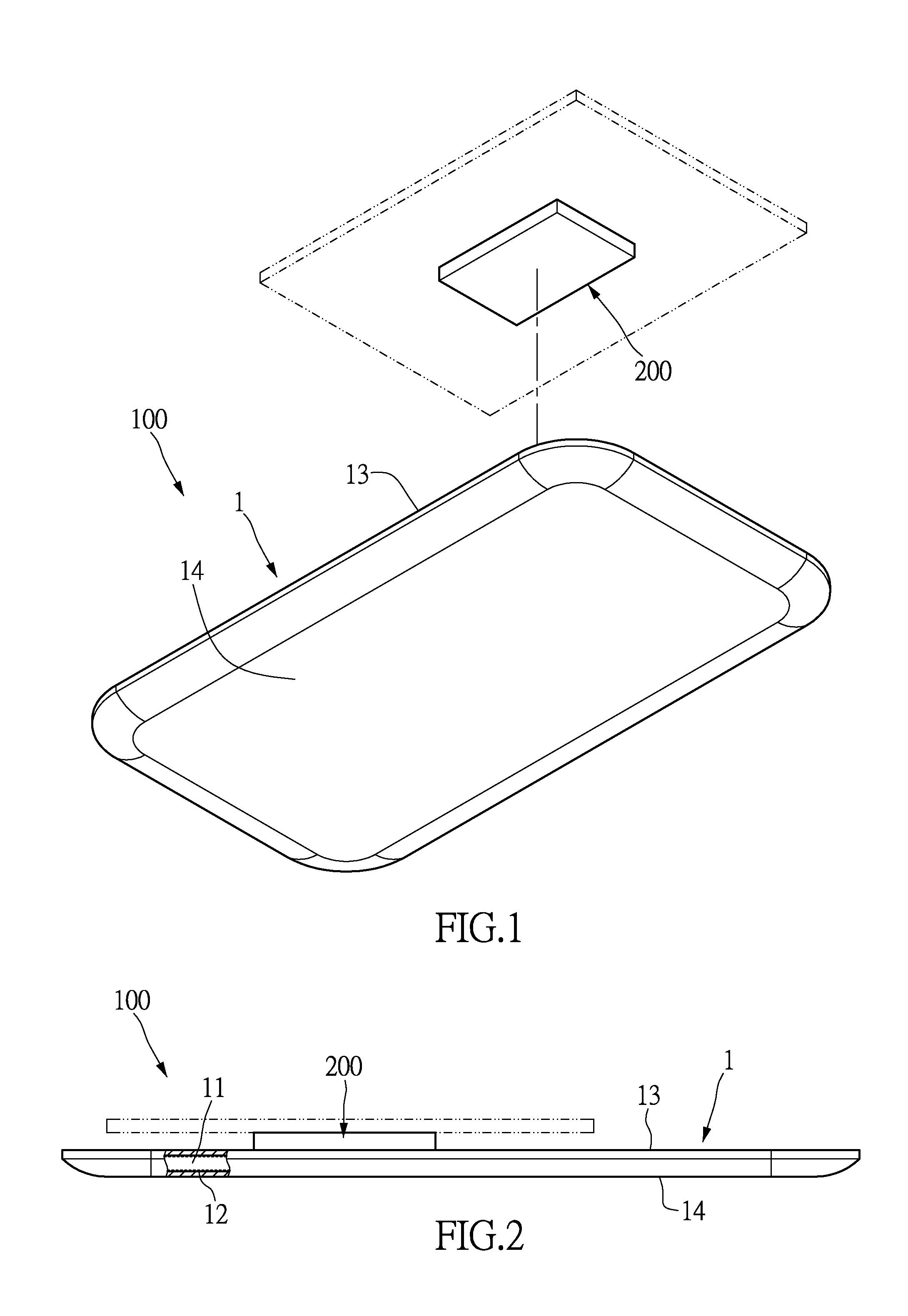
[0017]Referring to FIGS. 1 and 2, the instant disclosure provides a shell structure for handheld device. The handheld device can be a mobile phone, a tablet, a laptop, a personal digital assistance, a digital camera, an MP3 / MP4 multimedia player, an electronic device for games, or the like. The shell structure 100 can be the back cover, top cover, base or the other portion of the handheld device and the instant disclosure is not limited thereto. In the instant embodiment, the shell structure 100 is the back cover of a mobile phone.

[0018]At least one portion of the shell structure 100 is formed with a vapor chamber 1. That is, the entirety or a portion of the shell structure 100 is the vapor chamber 1. In the instant embodiment, the entire shell structure 100 is formed as the vapor chamber 1. In other words, the shell structure 100 defines the vapor chamber 1. The configuration of the vapor chamber 1 is not limited to the instant embodiment. The vapor chamber 1 can be configured to f...

second embodiment

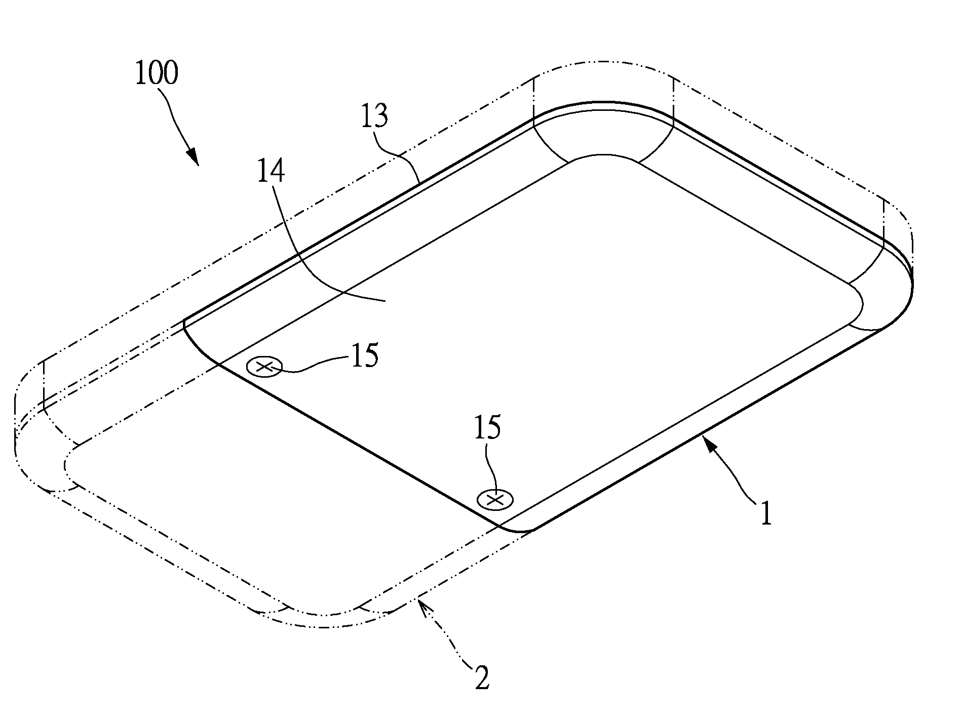
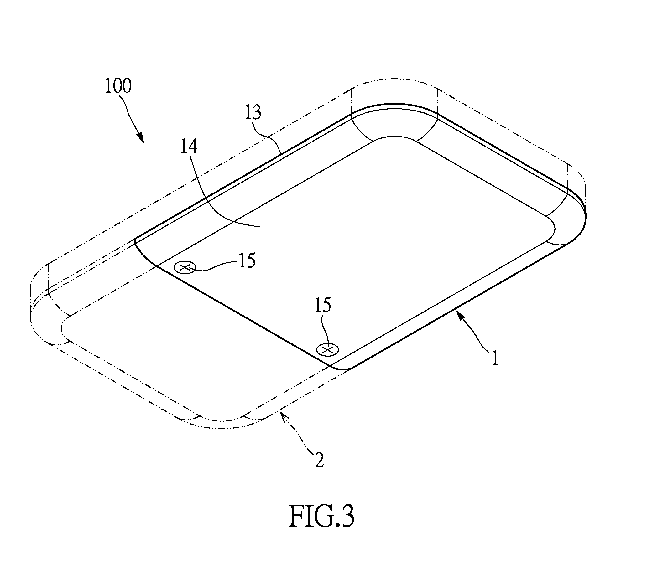
[0024]Referring to FIG. 3, a portion of the shell structure 100 is formed with the vapor chamber 1. That is, the shell structure 100 has a casing 2, and the vapor chamber 1 and the casing 2 are formed individually. The vapor chamber 1 and the casing 2 are connected by screws, press fit, plug-in, welding or adhesives. In the instant embodiment, the vapor chamber 1 and the casing 2 are connected by a plurality of screws 15. The vapor chamber 1 and casing 2 are not integrally formed and therefore the material thereof may vary. For example, the casing 2 can be made of metallic or plastic material.

third embodiment

[0025]Referring to FIG. 4, in the instant embodiment, the shell structure 100 is the back cover of a tablet. A portion of the shell structure 100 is formed with the vapor chamber 1. That is, the shell structure 100 has the casing 2, and the vapor chamber 1 and the casing 2 are formed individually. The casing 2 is configured to accommodate the vapor chamber 1 therein. The accommodating space 21 is visually integrated with the casing 2. The vapor chamber 1 and the casing 2 can also be connected by screws, press fit, plug-in, welding or adhesives.

[0026]In another embodiment of the instant disclosure, the shell structure 100 may have two or more vapor chamber 1 (not shown) accommodated in the casing 2. The vapor chambers 1 are arranged to contact the heat generating components in the handheld device.


PUM


Abstract

A shell structure for handheld device includes at least a portion of vapor chamber. The vapor chamber is formed with a heat absorbing portion and a heat dissipating portion. The vapor chamber is vacuumed and filled with fluid. A plurality of capillaries is formed in the vapor chamber. The heat from the handheld device is emitted rapidly by traveling through the vapor chamber without occupying the interior space of the handheld device.

Description

BACKGROUND[0001]1. Field of the Invention[0002]The instant disclosure relates to a shell structure; in particular, to a shell structure facilitating handheld device heat dissipation and maintaining optimal working temperature.[0003]2. Description of Related Art[0004]Conventional handheld devices (for example, mobile phones, tablets, personal digital assistance, and digital camera) require less power without the need of a heat sink. However, the electronic components still generate considerable amount of heat within the handheld device and the device temperature may climb in the future. Eventually, the installation of heat sink is unavoidable.[0005]To install heat sinks in a handheld device can occupy the relatively limited interior space. As a result, the device volume increases whereas the market requires an ever-thinning handheld device. Furthermore, the heat sinks embedded in the handheld device do not efficiently dissipate the heat and the unwanted heat accumulation usually lead...

Claims


Application Information

Patent Timeline
Patent Type & Authority Applications(United States)
IPC IPC(8): H05K7/20
CPCH05K7/20336G06F1/203
Inventor SUN, CHIEN-HUNGCHIN, TE-HSUAN
Owner COOLER MASTER DEVELOPMENT CORP
Why Eureka
Try Eureka