
Method of scrambling reference signals, device and user equipment using the method

a reference signal and signal technology, applied in the field of signal multiplexing method and reference signal design in communication system, can solve the problems of more severe impact of subband cqi calculations, inability to effectively reduce interference from other lpns, and imply very inaccurate interference power estimation of another lpn

Active Publication Date: 2014-12-04
SUN PATENT TRUST
View PDF4 Cites 20 Cited by
  • Summary
  • Abstract
  • Description
  • Claims
  • Application Information

AI Technical Summary

Benefits of technology

The patent text describes a way to keep signals from multiple locations fully or almost fully separate, so that interference between them can be minimized. This helps to detect and eliminate interference from a specific location while reducing interference from other locations.

Problems solved by technology

However, the current technique on interference measurement does not work well, because it can measure only the overall interference power (interference from all cells except the serving cell).
However, reusing OCCs and scrambling sequences have some drawback in heterogeneous networks, therefore a new OCC and scrambling may be further investigated.
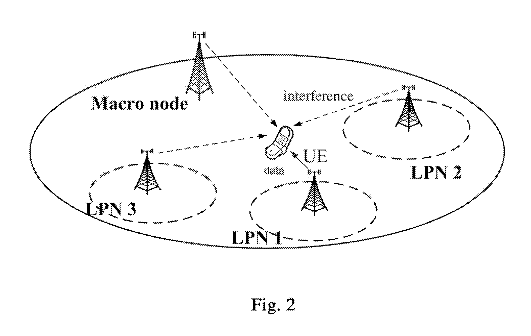
In this case, when the UE intends to estimate the interference power from another LPN via descrambling the related port, the residual interference from the macro node may be much higher than the interference power from the another LPN, which implies very inaccurate interference power estimation of the another LPN.
The impact is more severe for subband CQI calculations because of shorter scrambling sequences.
Especially, since Pmacro is much higher than LLPN2, the interference estimation for LPN2 is very inaccurate.

Method used


Image

  • Method of scrambling reference signals, device and user equipment using the method
  • Method of scrambling reference signals, device and user equipment using the method
  • Method of scrambling reference signals, device and user equipment using the method

Examples


first embodiment

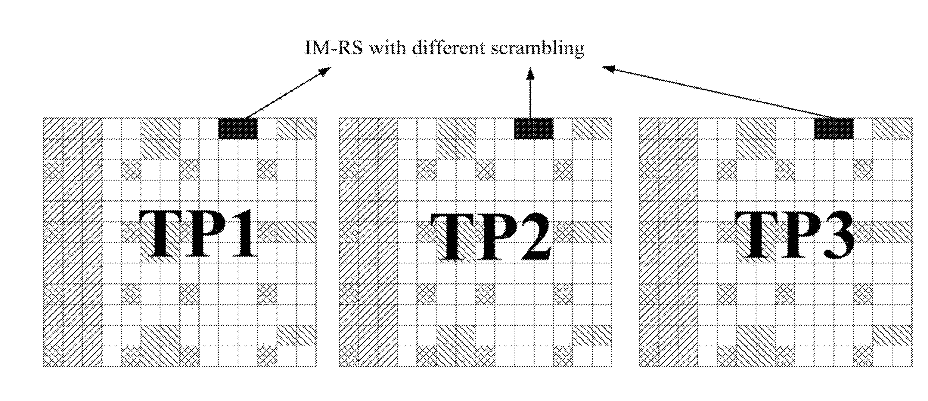
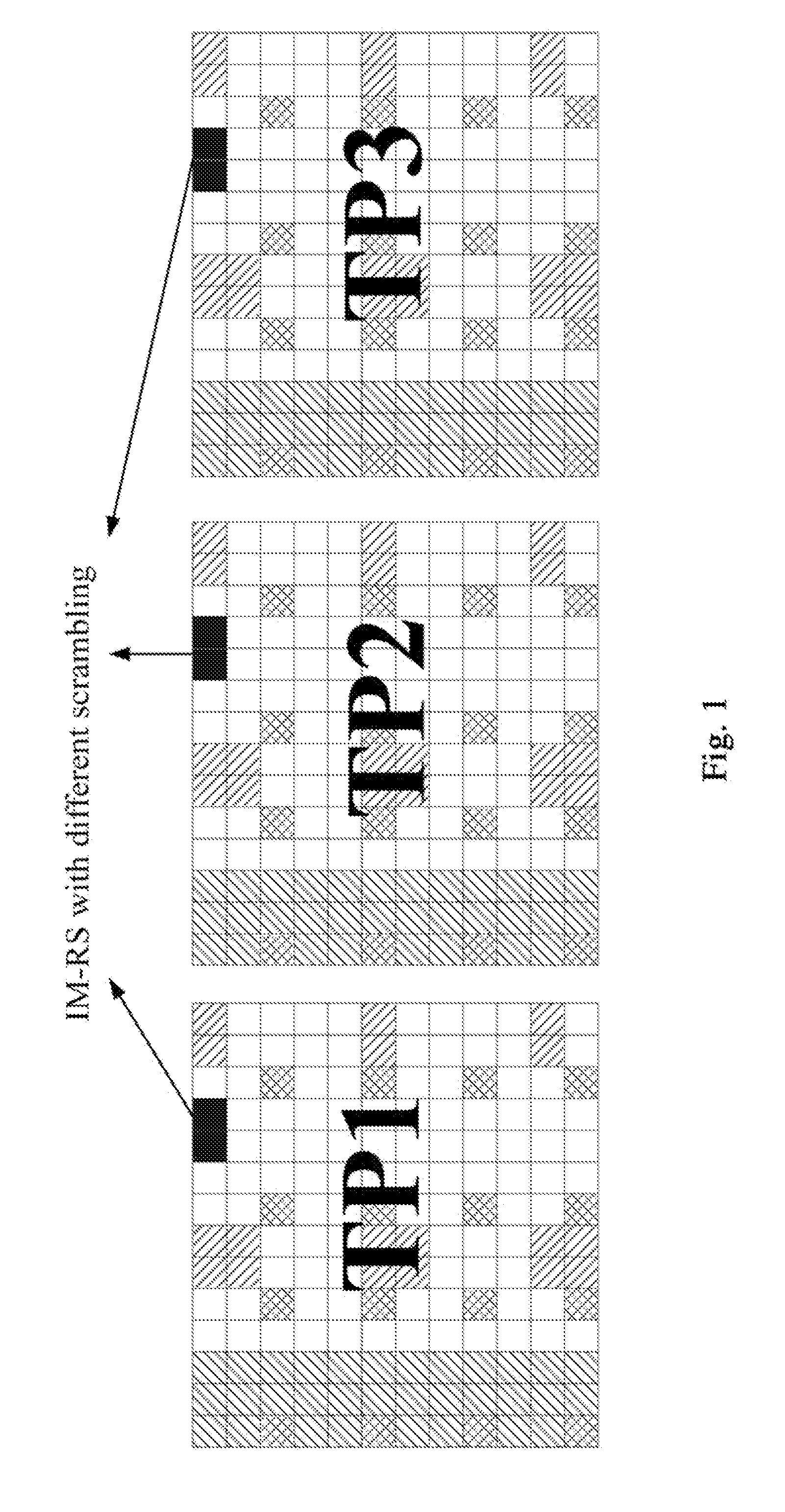
[0038]To reduce the interference among LPN ports, it is proposed to apply an additional scrambling sequence on each LPN port on the basis of the scrambling configuration for IM-RSs in FIG. 4. The additional scrambling sequence may be different for different LPNs to reduce the interference. Moreover, the additional scrambling sequence has to be common across the two symbols of OCC to maintain the orthogonality with the macro port, thus the additional scrambling sequence is called as symbol-common scrambling sequence hereinafter. FIG. 5 shows an example of scrambling configuration for IM-RSs from different TPs according to the first embodiment of the present disclosure. As compared with FIG. 4, the OCC and scrambling for the macro node is unchanged, that is, a single scrambling is performed on the macro node. On the other hand, for LPNs, on the basis of OCC and scrambling configuration in FIG. 4, a symbol-common scrambling sequence is further applied to each of LPNs, that is, a double...

second embodiment

[0056]In the method of the first embodiment as described above, since a single scrambling is applied on a macro node and a double scrambling is applied on each of LPNs, UE needs to distinguish the macro node and LPNs for the purpose of accurate descrambling. In general, UE does not know which TP is a macro node and which TP is a LPN. Thus, it is preferred to adopt the same scrambling format for a macro node and a LPN. In the present embodiment, it is proposed to apply double scrambling on both LPN and macro node so as to avoid informing UE which transmission point is the macro node.

[0057]FIG. 10 shows an example of scrambling configuration for IM-RSs from different TPs according to the second embodiment of the present disclosure. As shown in FIG. 10, there are configured two sets of IM-RSs, i.e. IM-RS set 1 and IM-RS set 2. Each IM-RS in the set 1 is assigned with the length-2 OCC [1, 1] while each IM-RS in the set 2 is assigned with the OCC [1, −1]. Thus, by the above OCC configura...

third embodiment

[0063]The above two embodiments are both related to length-2 OCCs. However, the present disclosure is not limited to this and may be extended to length-4 OCCs and so on. As an example, the present embodiment is to apply double scrambling to length-4 OCCs. Note that, 4 port CSI-RS is adopted on two adjacent OFDM symbols and two subcarriers that are six subcarriers away on a resource block.

[0064]FIG. 12 shows an example of scrambling configuration for IM-RSs from different TPs according to the third embodiment of the present disclosure. FIG. 12 is to extend the concept in the above embodiment to a length-4 OCC case. Specifically, as shown in FIG. 12, IM-RS from a macro node is assigned with a length-4 OCC [1, 1, 1, 1], IM-RSs from LPN1 and LPN4 are assigned with a length-4 OCC [1, −1, 1, −1], IM-RSs from LPN2 and LPN5 are assigned with a length-4 OCC [1, 1, −1, −1], and IM-RSs from LPN3 and LPN6 are assigned with a length-4 OCC [1, −1, −1, 1]. Thus, IM-RSs from LPNs are kept fully ort...


PUM


Abstract

A Method of scrambling reference signals, device and user equipment using the method are provided. In the method, a plurality of layers of reference signals assigned on predetermined radio resource of a plurality of layers of resource blocks with the same time and frequency resources are scrambled, the method comprising: an orthogonalizing step of multiplying each layer of reference signal selectively by one of a plurality of orthogonal cover codes (OCCs) with the same length wherein the OCC multiplied to a first layer of reference signal can be configured as different from those multiplied to other layers of reference signals; and a scrambling step of multiplying all of symbols obtained from the OCC multiplied to each of the other layers of reference signals by a symbol-common scrambling sequence wherein the symbol-common scrambling sequences can be different from each other for reference signals multiplied by the same OCC.

Description

TECHNICAL FIELD[0001]The present disclosure relates to the field of signals multiplexing method and reference signal design in communication system.BACKGROUND[0002]The cooperation between base stations is an important means to mitigate inter-cell-interference in cellular systems and is being intensively discussed in the fourth generation of wireless communication system standardizations. It is important for the specifications to enable flexible CoMP (Coordinate Multiple Points) operations, such as JT (joint transmission), coordinated beamforming, and dynamic point selection, etc.[0003]It is noted that different CoMP operations require different CQI (Channel Quality Indicator) calculation assumptions. For example, for JT transmission, a UE (user equipment) would assume the signal power is from multiple cells (transmission points) that transmit PDSCHs (Physical Downlink Shared Channels) to the UE, while other cells are interfering cells. But, for CB (coordinated beamforming) transmiss...

Claims


Application Information

Patent Timeline
Patent Type & Authority Applications(United States)
IPC IPC(8): H04L5/00H04L25/03
CPCH04L25/03866H04L5/0048H04J13/0003H04J13/004H04J13/18H04L5/0025H04L27/2613H04B7/0684H04B7/024H04J2211/005
Inventor TONG, HUIHOSHINO, MASAYUKIXU, MINGIMAMURA, DAICHI
Owner SUN PATENT TRUST
Learn More