
Migration of Application Components

Inactive Publication Date: 2014-12-04
UNIV DE PAU & DU PAYS DE LADOUR
View PDF8 Cites 17 Cited by
  • Summary
  • Abstract
  • Description
  • Claims
  • Application Information

AI Technical Summary

Benefits of technology

The invention is a supervision system that allows components to be moved between devices without affecting the communication of other components. This allows for dynamic and transparent sharing of resources in mobile or constrained environments. The main technical effect is improved system flexibility and efficiency.

Problems solved by technology

The challenge is to be able to propose applications for these devices which adapt both to the wishes of the users and to the physical environment in which they operate.
However, these devices possess characteristics (energy autonomy, mobility, limited resources) which necessitate the adaptation of the applications as well as of the services rendered by the latter to ensure correct operation for a sufficient duration, and service continuity in case of unavailability of a peripheral of the electronic device, for example when a peripheral of the electronic device no longer possesses sufficient battery.
This may result in limited comfort of use for the user, notably in the case where applications are currently executing.
However, the OSGi platform does not support the migration of components between peripherals and is based on the discovery of services.
None of the proposed approaches allows entirely dynamic and transparent decentralized supervision of the application components on a set of mobile devices, that could be of different kinds and connected by all types of networks, as a function of context.
Moreover, none of the existing solutions proposes such a supervision system capable of carrying out the migration of software components in mobile environments.

Method used


Image

  • Migration of Application Components
  • Migration of Application Components
  • Migration of Application Components

Examples


Embodiment Construction

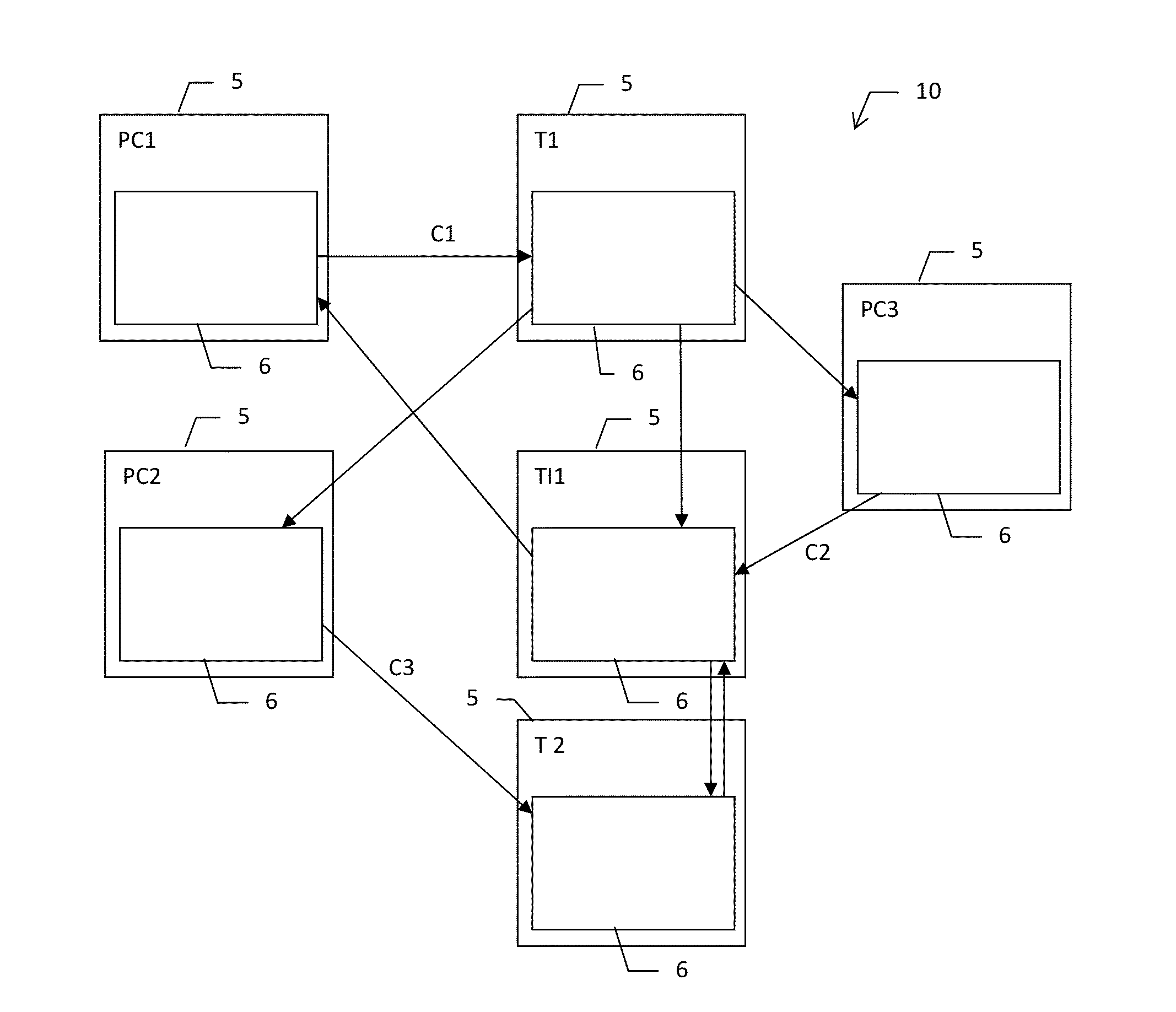
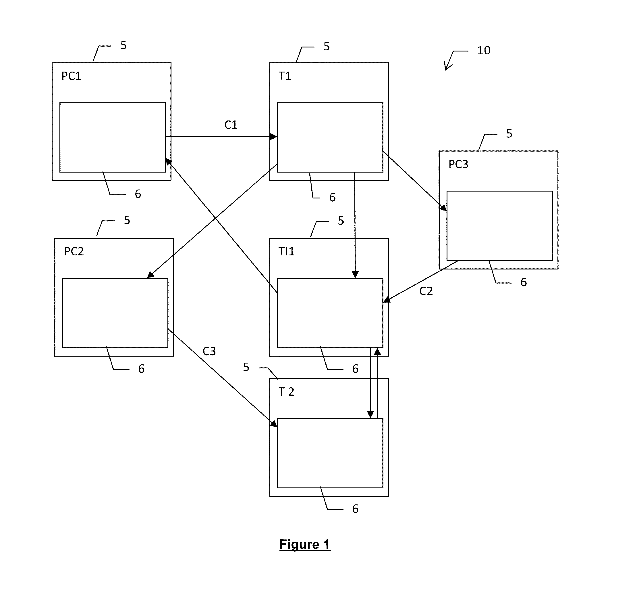
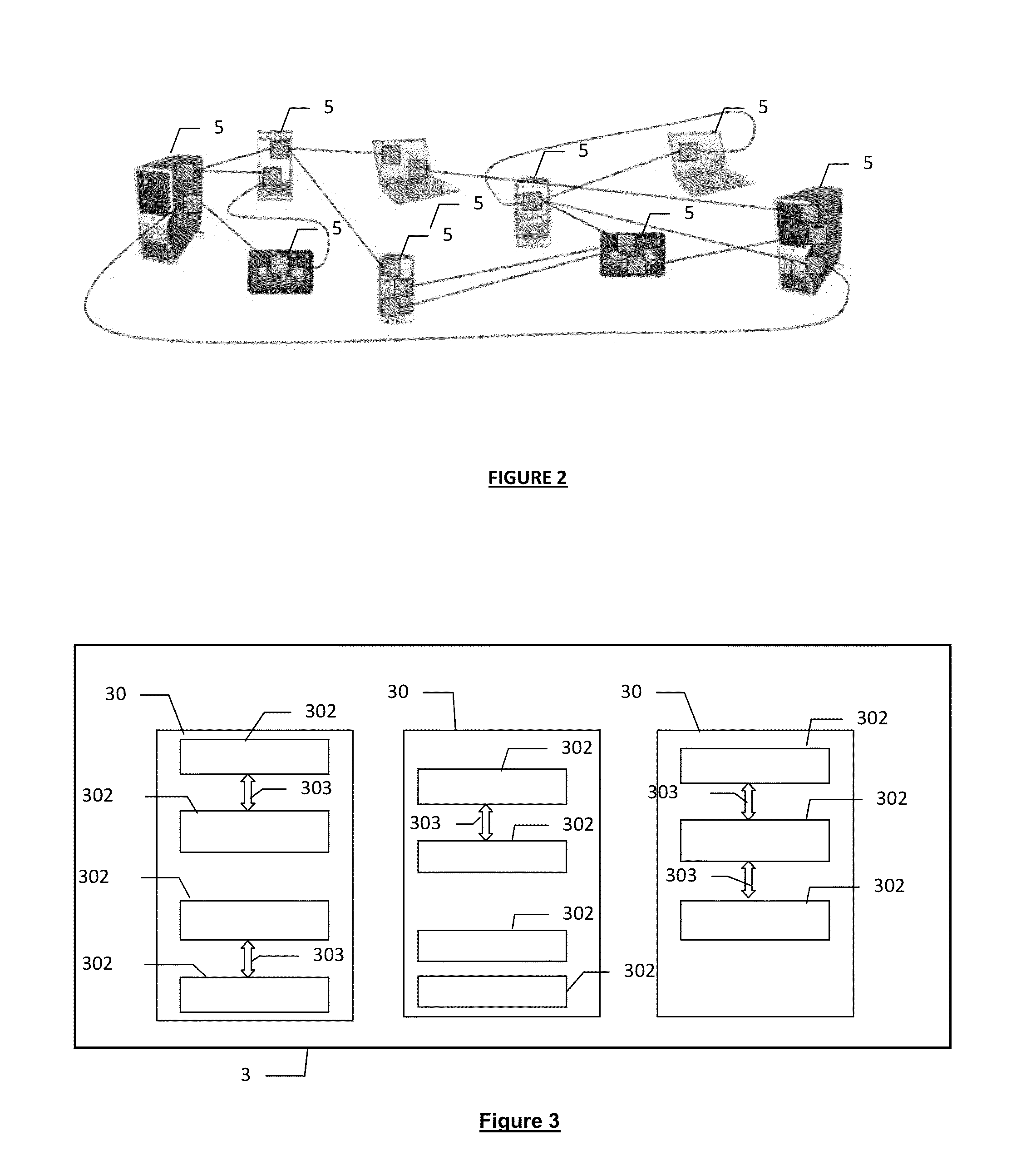
[0071]FIG. 1 represents a system for supervising applications 10 implementing the dynamic loading process according to the embodiments of the invention. The supervision system 10 represented is a dynamic and decentralized system for controlling the applications of a set of electronic devices 5 connected together by communication networks, for example of WIFI or satellite type (GSM, 3G, etc.). The electronic devices (also designated by the expressions “host devices” or “hosts” or “machines” in the subsequent description) can comprise any type of electronic device, notably mobile electronic devices, such as personal computers such as PC1 and PC2, intelligent mobile telephones (called “Smartphones”) such as T1 and T2, computer tablets such as TI1, etc. The communication networks supported by the electronic devices 5 can comprise several types of networks.

[0072]According to this decentralized approach, the supervision system 10 comprises a set of supervision entities 6 (also called “loc...


PUM


Abstract

A system supervises applications executing on electronic devices connected by one or more networks. Each device comprises a local supervision entity, cooperating to control the applications. Each application comprises a set of application components, each encapsulated in a container by the supervision entity of the device hosting the component. The components are connected by connectors. The supervision entity of a source device executes, in response to receipt of a command to migrate a component to a target device: stopping the component, interrupting arrival of data in the input connectors of the component, serializing and encapsulating the properties of the component in a container of the supervision entity, dispatching a migration request message to the supervision entity of the target device, the message comprising the serialized and encapsulated component, and redirecting the connectors of the component as a function of the state of connections of each connector on the source device.

Description

CROSS-REFERENCE TO RELATED APPLICATION[0001]This application claims priority to foreign French patent application No. FR 1354889, filed on May 29, 2013, the disclosure of which is incorporated by reference in its entirety.FIELD OF THE INVENTION[0002]The present invention generally relates to mobile electronic devices and in particular to a process and a system for supervising application components.BACKGROUND[0003]Recent technological advances over the last few years have placed the emphasis on the democratization of wireless networks and on the miniaturization of communication kit. Currently, there exists on the market a multitude of personal electronic devices that are ever more lightweight, compact, mobile and endowed with diverse means of wireless communication, such as portable telephones, intelligent mobile telephones (“smartphones”), tablets, laptop computers or else sensors. These devices concentrate complex and very diversified functionalities: telephony, instant messaging,...

Claims


Application Information

Patent Timeline
IPC IPC(8): H04L12/24
CPCH04L41/50H04L67/34G06F9/44521G06F9/4856H04L67/10H04L41/0816H04L43/0811H04L43/10Y02D10/00
Inventor DALMAU, MARCROOSE, PHILIPPE
Owner UNIV DE PAU & DU PAYS DE LADOUR
Learn More