Factory fabricated precompressed water and/or fire resistant tunnel expansion joint systems, and transitions

a technology of prefabricated transitions and expansion joints, applied in the field of joint systems, can solve the problems of difficult or impossible prefabrication of expansion joints, many expansion joints do not fully consider the irregular nature of building expansion joints, and may be subject to pedestrian and/or vehicular traffic in horizontal systems, etc., to achieve the effect of on-site operations

Inactive Publication Date: 2014-12-11
EMSEAL JOINT SYST
View PDF24 Cites 96 Cited by
  • Summary
  • Abstract
  • Description
  • Claims
  • Application Information

AI Technical Summary

Benefits of technology

[0014]In any embodiment, the construction or assembly of the systems described herein is generally carried out off-site, but elements of the system may be trimmed to appropriate length on-site. By constructing or assembling the systems of the present invention in a factory setting, on-site operations typically carried out by an installer (who may not have the appropriate tools or training for complex installation procedures) can be minimized. Accordingly, the opportunity for an installer to effect a modification such that the product does not perform as designed or such that a transition does not meet performance expectations is also minimized.

Problems solved by technology

Additionally, some horizontal systems may be subjected to pedestrian and / or vehicular traffic.
Many expansion joint products do not fully consider the irregular nature of building expansion joints.
In many products, this is a point of weakness, as the homogeneous nature of the product is interrupted.
In many situations, it is difficult or impossible to prefabricate these expansion joint transitions, as the exact details of the expansion joint and any transitions and / or dimensions may not be known at the time of manufacturing.
In the first situation, there is a chance that a person installing the product does not possess the adequate tools or knowledge of the product to modify it in a way such that the product still performs as designed or such that a transition that is commensurate with the performance expected thereof can be effectively carried out.
This can lead to a premature failure at the point of modification, which may result in subsequent damage to the property.
Both return to the manufacturer and scrapping and re-manufacture are costly, and both result in delays with regard to the building construction, which can in itself be extremely costly.

Method used


Image

  • Factory fabricated precompressed water and/or fire resistant tunnel expansion joint systems, and transitions
  • Factory fabricated precompressed water and/or fire resistant tunnel expansion joint systems, and transitions
  • Factory fabricated precompressed water and/or fire resistant tunnel expansion joint systems, and transitions

Examples


Embodiment Construction

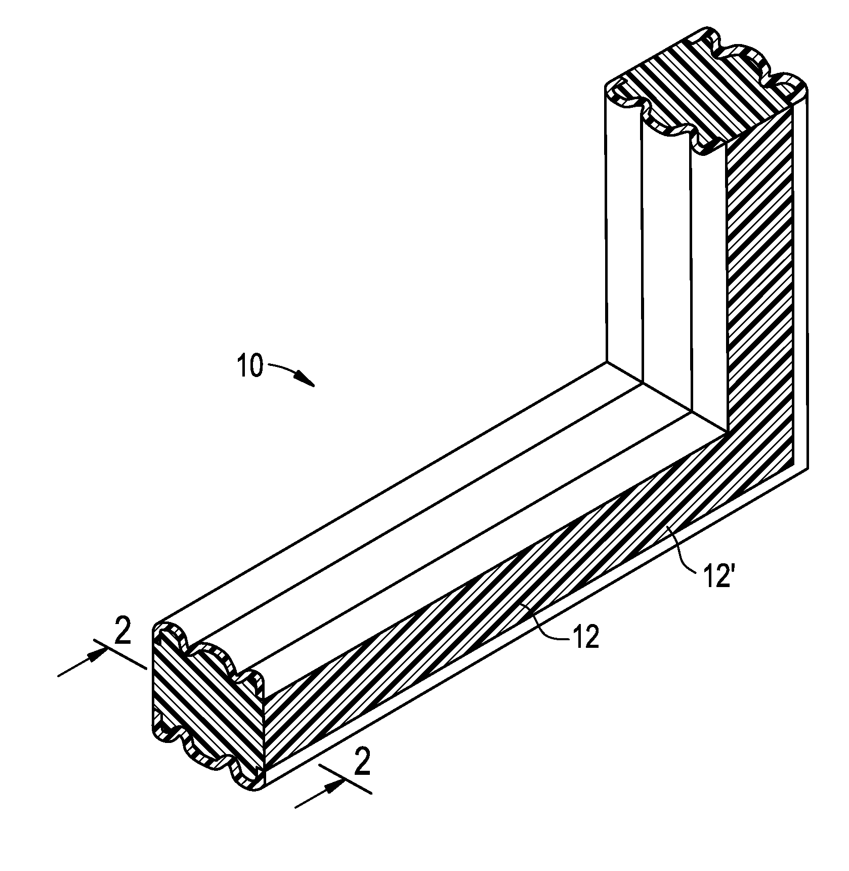
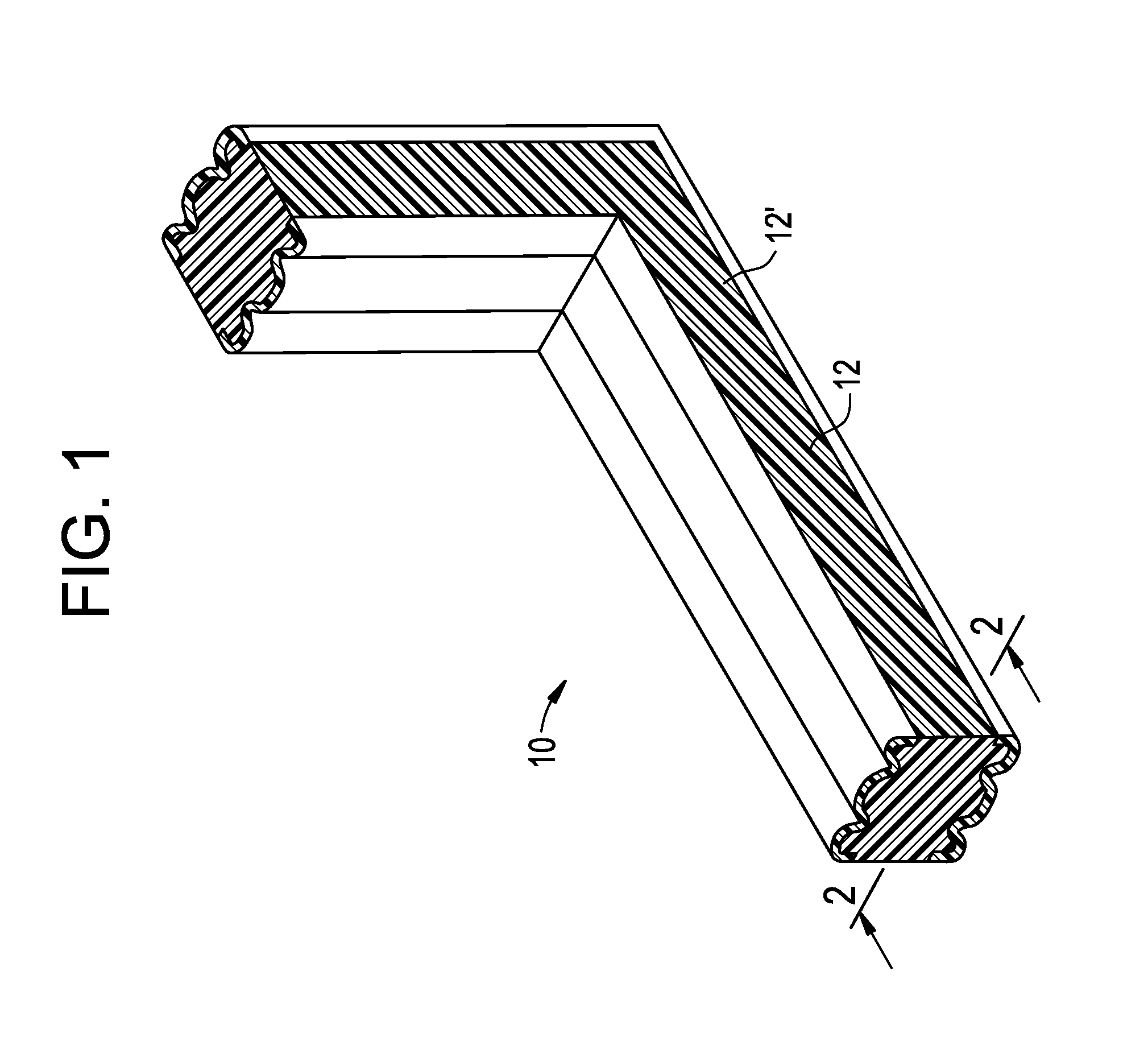
[0033]Embodiments of the present invention provide a resilient water resistant and / or fire resistant expansion joint system able to accommodate thermal, seismic, and other building movements while maintaining water resistance and / or fire resistance characteristics. Embodiments of present invention are especially suited for use in concrete buildings and other concrete structures including, but not limited to, parking garages, stadiums, tunnels including tunnel walls, floors and tunnel roofs, bridges, waste water treatment systems and plants, potable water treatment systems and plants, and the like.

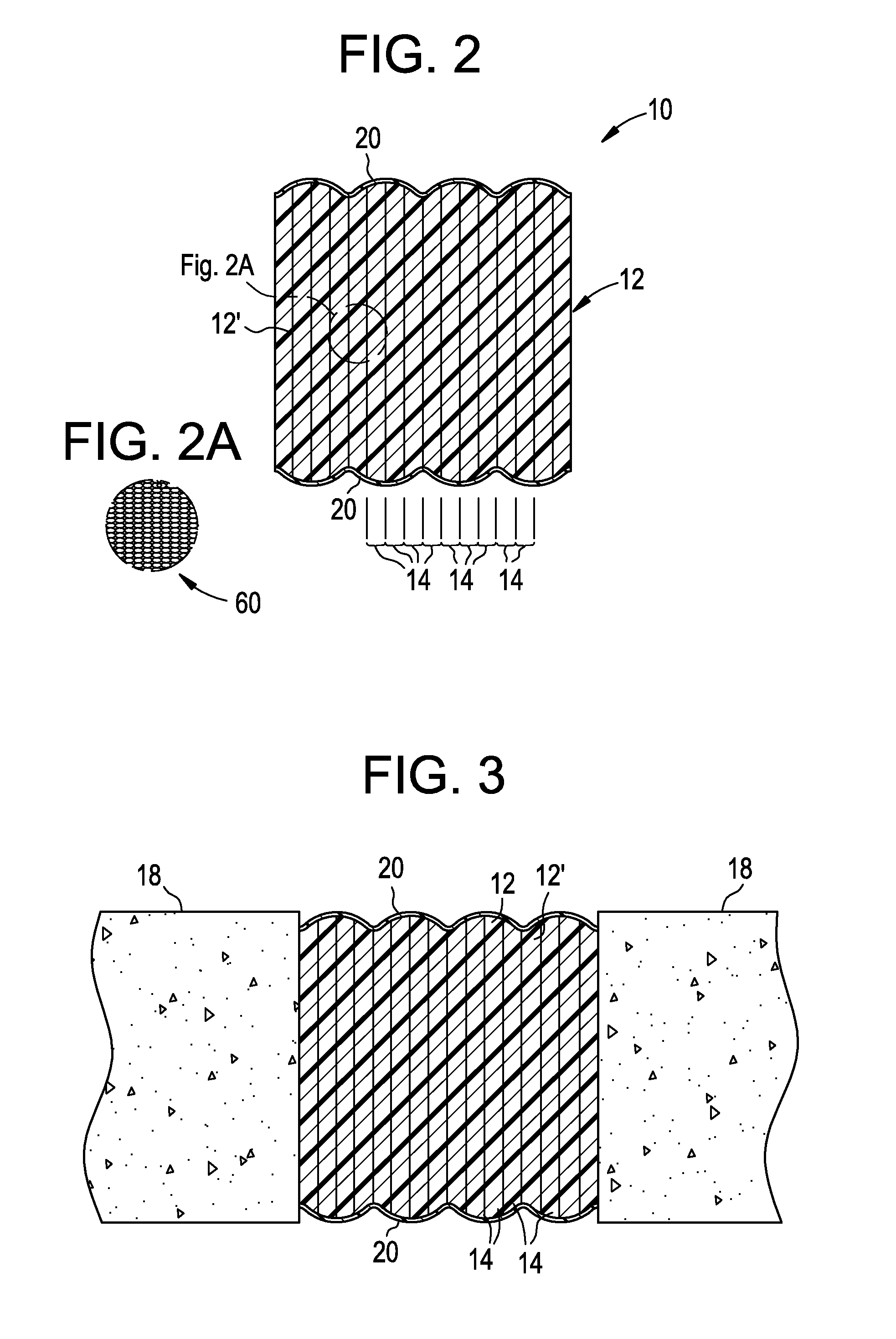
[0034]Referring now to FIGS. 1-3, embodiments of the present invention include an expansion joint system oriented in a vertical plane and configured to transition corners at right angles. This system is designated generally by the reference number 10 and is hereinafter referred to as “vertical expansion joint system 10.” It should be noted, however, that the vertical expansion joint system ...


PUM


Abstract

A fire and/or water resistant expansion joint system for installation between substrates of a tunnel. The system includes a coating applied at a predetermined thickness to the substrates and a fire and water resistant expansion joint. The expansion joint includes a core and a fire retardant infused into the core. The core is configured to define a profile to facilitate the compression of the expansion joint system when installed between the substrates. The coating and the fire and water resistant expansion joint are each capable of withstanding exposure to a temperature of at least about 540° C. or greater for about five minutes.

Description

CROSS REFERENCE TO RELATED APPLICATION[0001]This patent application claims priority benefit under 35 U.S.C. §119(e) of copending, U.S. Provisional Patent Application Ser. No. 61 / 806,194, filed Mar. 28, 2013, the disclosure of which is incorporated by reference herein in its entirety. This application also claims priority benefit under 35 U.S.C. §120 of copending, U.S. Non-provisional patent application Ser. No. 13 / 731,327, filed on Dec. 31, 2012 (attorney docket no. 1269-0002-1CIP), which is a Continuation-in-Part Application of U.S. patent application Ser. No. 12 / 635,062, filed on Dec. 10, 2009 (attorney docket no. 1269-0002-1), which claims the benefit of U.S. Provisional Patent Application No. 61 / 121,590, filed on Dec. 11, 2008, the contents of each of which are incorporated herein by reference in their entireties and the benefits of each are fully claimed. This application also claims priority benefit under 35 U.S.C. §120 of copending, U.S. Non-provisional patent application Ser...

Claims


Application Information

Patent Timeline
Patent Type & Authority Applications(United States)
IPC IPC(8): E04B1/94
CPCE04B1/948E04B1/6812E21D11/385E02D29/045E04B1/6815E04B2001/6818
Inventor HENSLEY, LESTERWITHERSPOON, WILLIAM
Owner EMSEAL JOINT SYST
Why Eureka
Try Eureka