Systems and Methods for Electric and Heat Generation from Biomass

a technology of electric and heat generation and biomass, which is applied in the direction of combustion types, lighting and heating apparatuses, machines/engines, etc., can solve the problems of significant difficulties in using biomass over fossil fuels

Inactive Publication Date: 2014-12-11
WARMBOLD D STUBBY
View PDF9 Cites 6 Cited by
  • Summary
  • Abstract
  • Description
  • Claims
  • Application Information

AI Technical Summary

Problems solved by technology

Although the use of biomass in power generation is promising, there are significant difficulties in using biomass over fossil fuels, since biomass generally has less energy content per unit mass than fossil fuels.

Method used


Image

  • Systems and Methods for Electric and Heat Generation from Biomass
  • Systems and Methods for Electric and Heat Generation from Biomass
  • Systems and Methods for Electric and Heat Generation from Biomass

Examples


Embodiment Construction

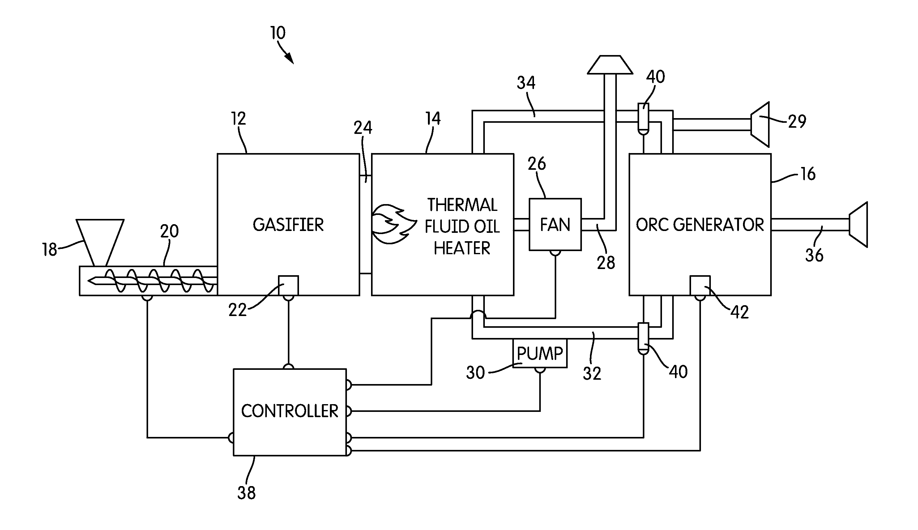
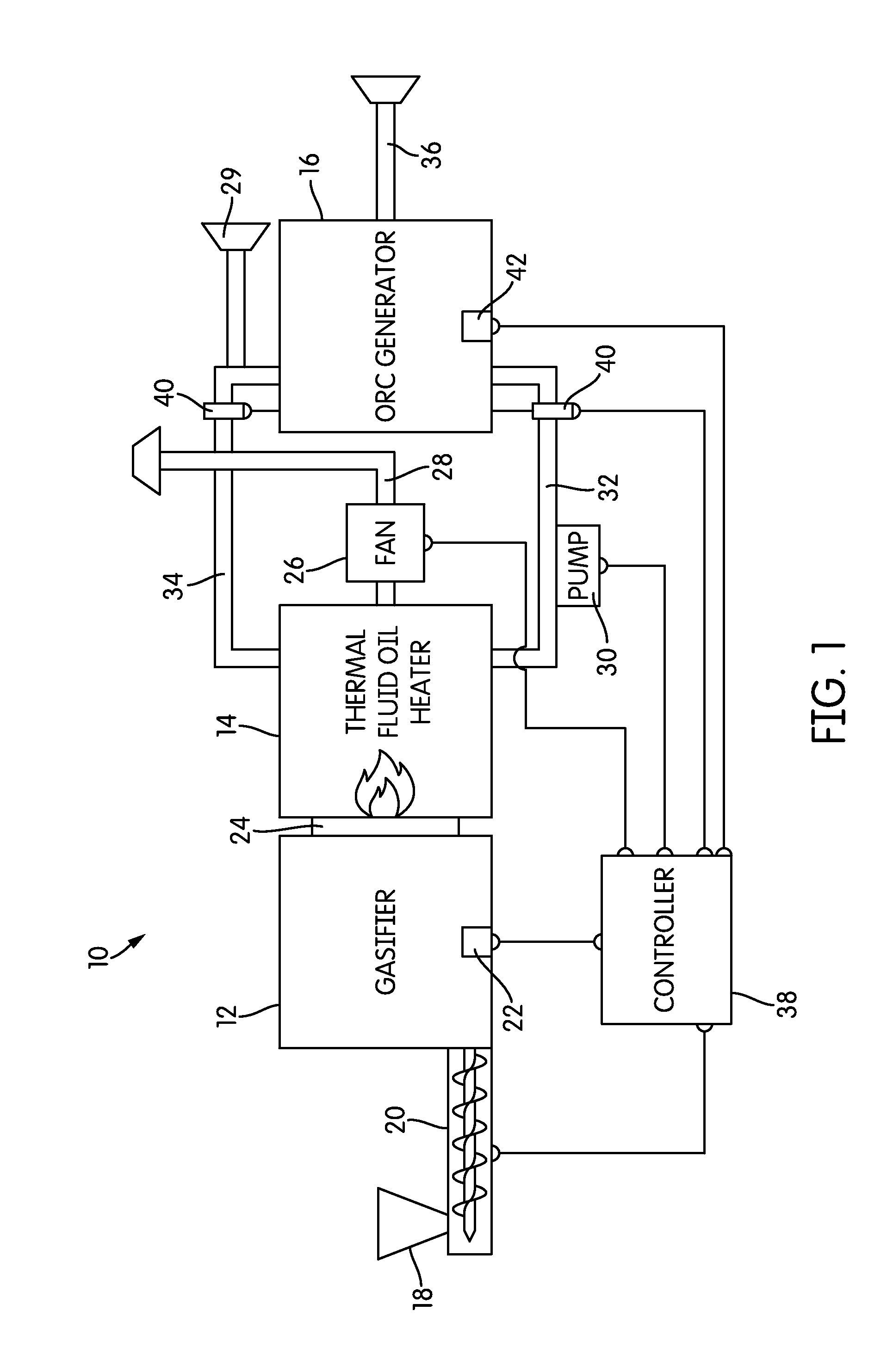
[0014]FIG. 1 is a schematic illustration of a system for producing power, generally indicated at 10, according to an embodiment of the invention. System 10 is particularly adapted to use biomass as a primary fuel, and combines three technologies to produce power: a gasifier 12, a thermal fluid oil heater 14, and a generator that uses the organic Rankine cycle 16.

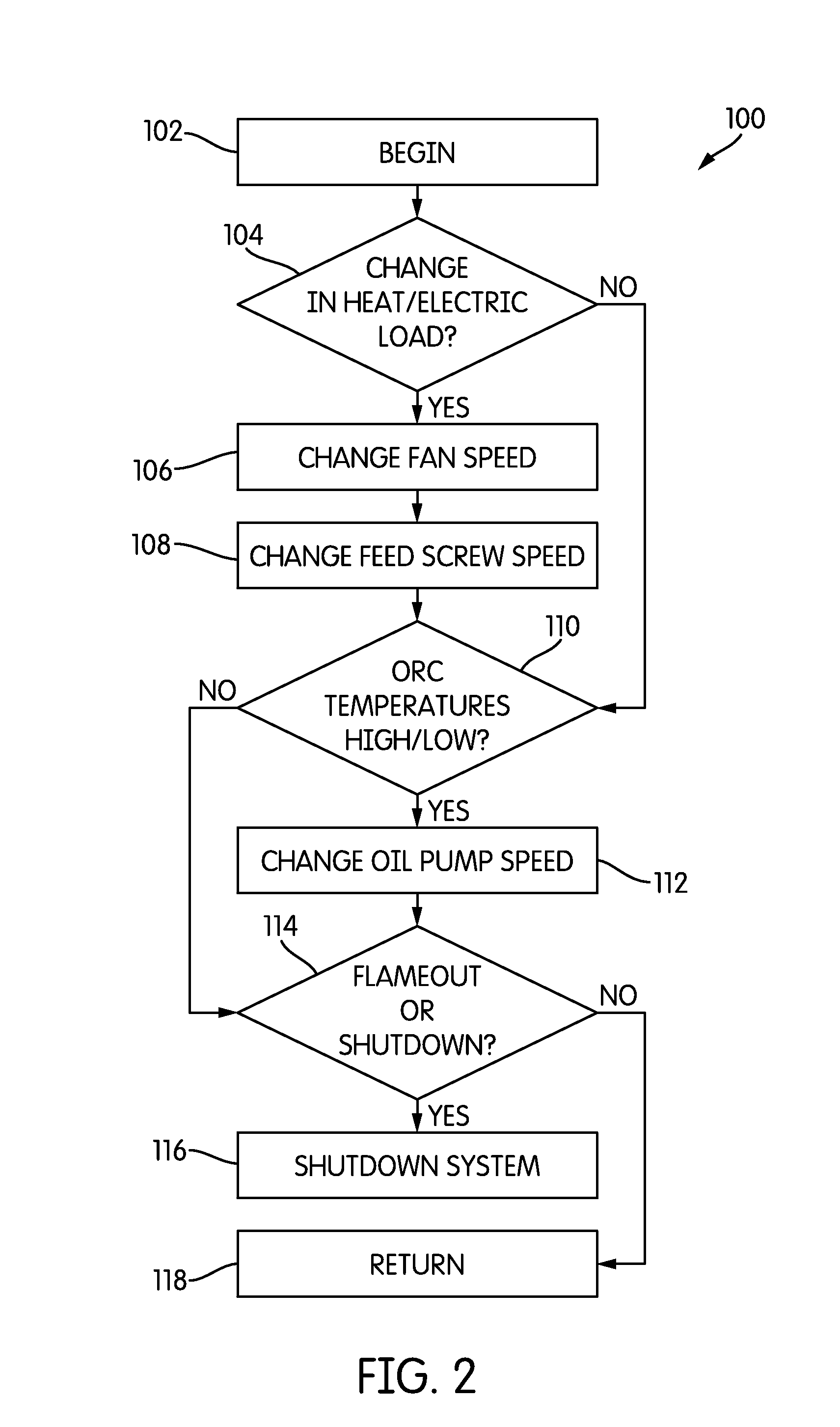
[0015]The process of producing power begins when a user adds biomass to a feed hopper 18. As used here, the term “biomass” refers to any plant-based material that may be used as a fuel. The biomass fuel drops or is fed into a feed screw 20 which is driven by a variable and controllable speed motor (not shown in FIG. 1). As the feed screw 20 turns, the biomass fuel is fed into the gasifier 12 at a defined rate. As will be described below in more detail, the feed rate may be increased or decreased as necessary.

[0016]The gasifier 12 of the illustrated embodiment is a cross-draft gasifier, although essentially any type of gasifi...


PUM


Abstract

A system for producing energy and heat from biomass is disclosed. The system includes a feed system, a gasifier, a thermal fluid oil heater, and a generator based on the organic Rankine cycle (ORC). The system may also include a controller that takes input from a number of sensors and controls, among other things, the rate at which fuel is fed into the system and the speed of fans and pumps that draw the products from one apparatus into the next. In this system, the biomass is fed into the gasifier, the resulting producer gas is flared and used to heat an oil in the thermal fluid oil heater, and the hot oil is used to provide input heat for the ORC generator. Methods for controlling such a system are also disclosed.

Description

CROSS-REFERENCE TO RELATED APPLICATIONS[0001]This application is a continuation-in-part of U.S. application Ser. No. 12 / 927,406, filed Nov. 15, 2010, the contents of which are incorporated by reference in their entirety.BACKGROUND OF THE INVENTION[0002]1. Field of the Invention[0003]The invention relates to systems and methods for electric and heat generation from biomass.[0004]2. Description of Related Art[0005]Industrial systems for producing power are well known. In the most general terms, typical processes for generating electrical energy involve burning a fossil fuel that heats a working fluid to drive a turbine. The spinning turbine generates electricity. In order to produce power with high efficiency, the temperatures and pressures used in a typical power production cycle are generally very high.[0006]In recent years, there has been a greater focus on the use of renewable energy sources, rather than fossil fuels, in power generation processes. One particular source of biofuel...

Claims


Application Information

Patent Timeline
Patent Type & Authority Applications(United States)
IPC IPC(8): F23G5/027F01K13/02F01K25/08F23G5/46
CPCF23G5/0276F23G5/46F23G2206/203F01K25/08F01K13/02F23G5/50F23G7/10F23G2201/303F23G2201/40F23G2205/121F23G2207/101F23G2207/20F23G2208/00F23N2225/20F23N2225/21F23N2229/00F23N2233/04Y02E20/12
Inventor WARMBOLD, D. STUBBY
Owner WARMBOLD D STUBBY
Why Eureka
Try Eureka