
Toroidal heat exchanger

a heat exchanger and tetrahedron technology, applied in the field of tetrahedron heat exchangers, can solve the problems of inability to work with toroidal combustion chambers, limited capacity of current heat exchangers to handle high temperature oxidizing and/or corrosion environments, and inability to effectively extract heat, etc., to achieve cost-effective and simplified heat exchangers, flexible capacity, and effective extraction

Inactive Publication Date: 2014-12-11
C6 COMBUSTION TECH LP
View PDF9 Cites 0 Cited by
  • Summary
  • Abstract
  • Description
  • Claims
  • Application Information

AI Technical Summary

Benefits of technology

The patent is about a heat exchanger that is designed to extract heat from exhaust gases and use it to expel a de-energized combustion product. The device is made using advanced materials and can be easily expanded or reduced in size without machining. The flow through the device is smooth and without sudden direction changes, which reduces flow resistance and prevents buildup of tar. The "technical effect" of this design is a flexible, modular heat exchanger that is efficient and effective at extracting heat from exhaust gases.

Problems solved by technology

Current heat exchangers have limited capabilities to handle high temperature oxidizing and / or corrosive environments.
The current heat exchanger technologies in this field are also extremely expensive.
Current heat exchangers are ill-suited to work with toroidal combustion chambers due to various geometry, size, and functionality concerns.

Method used


Image

  • Toroidal heat exchanger
  • Toroidal heat exchanger
  • Toroidal heat exchanger

Examples


Embodiment Construction

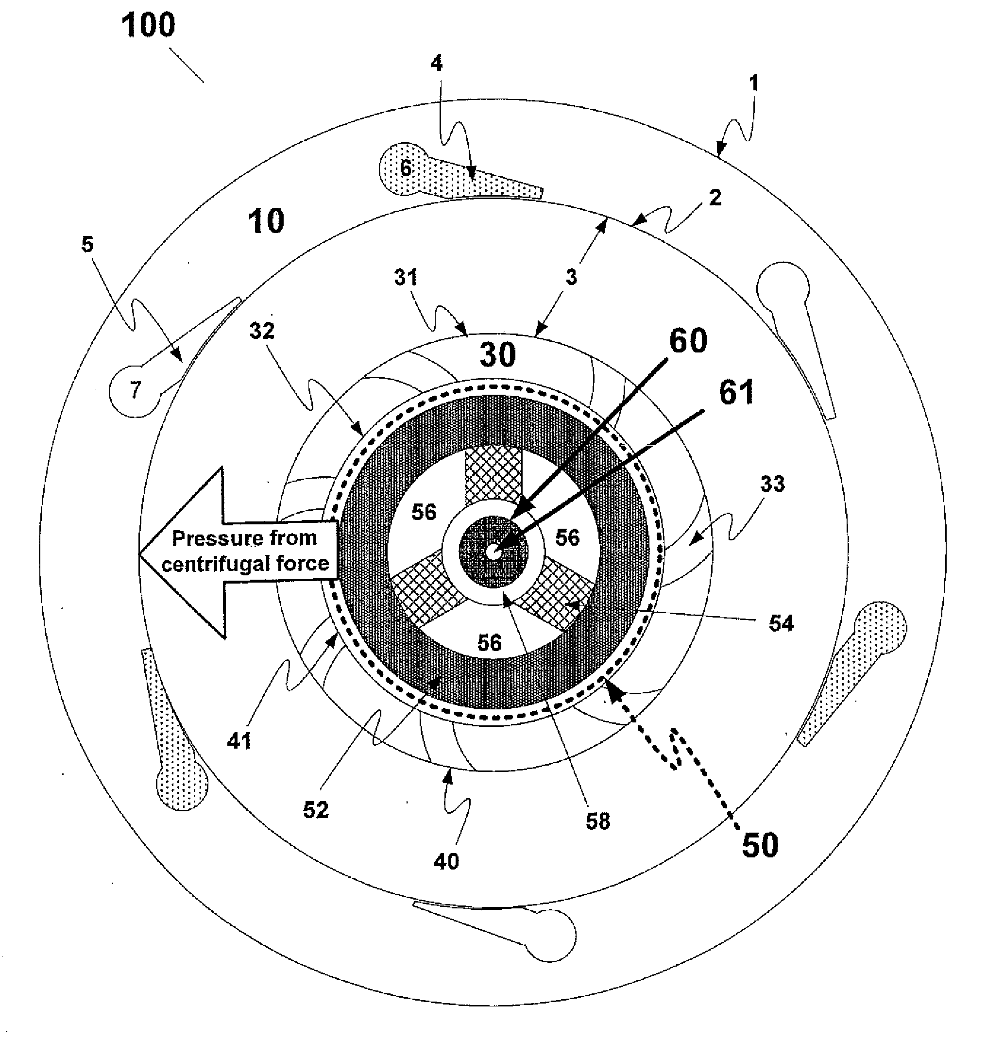
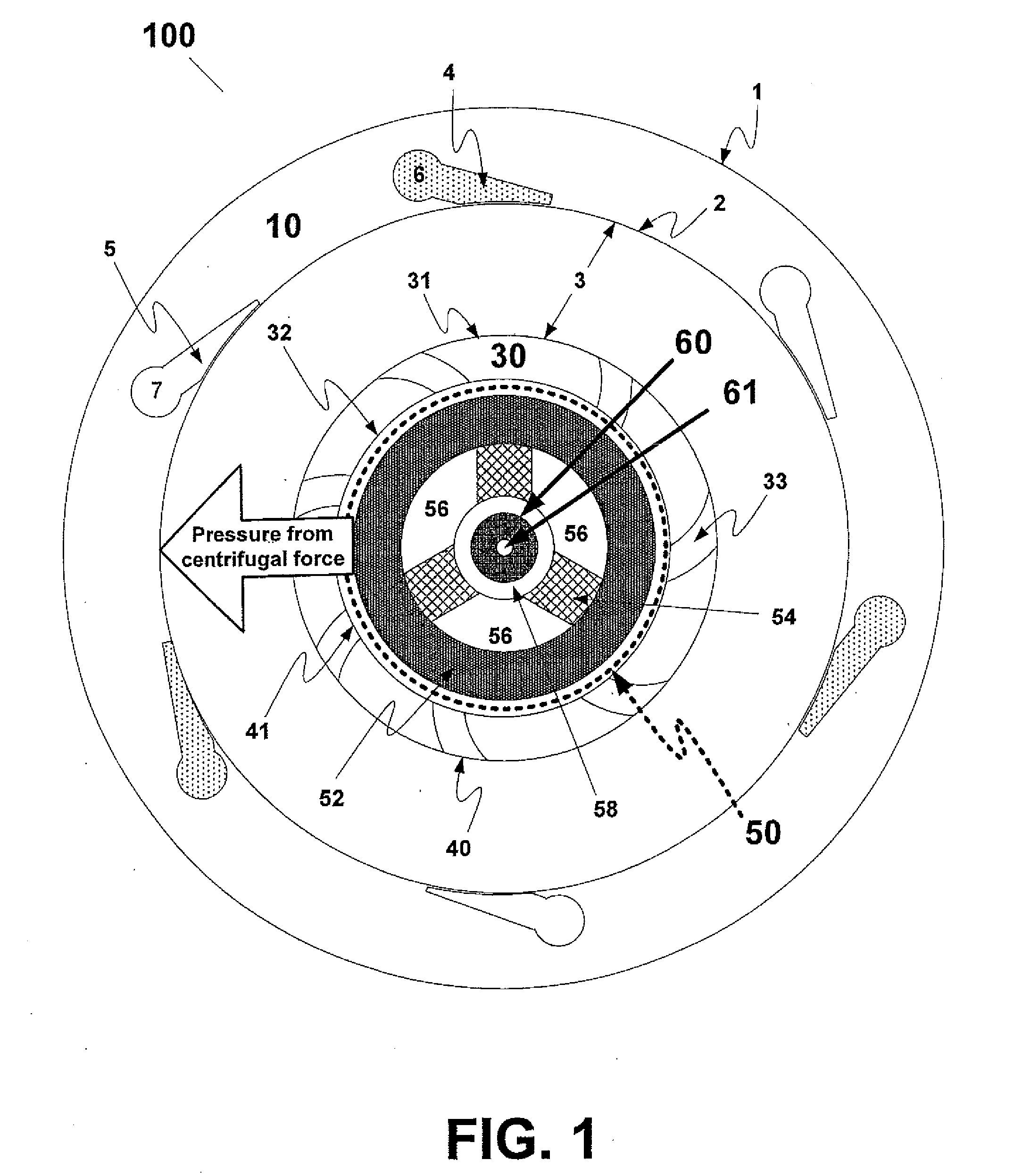
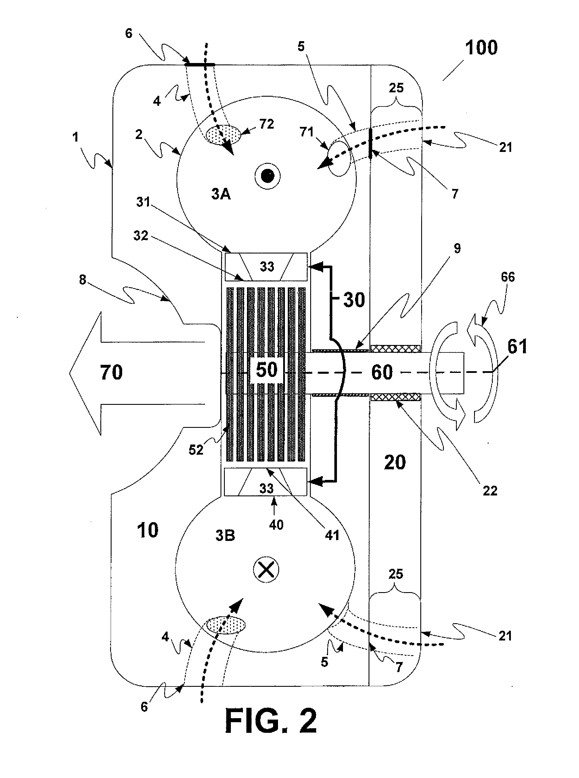
[0023]FIG. 1 illustrates a turbine 100, which may comprise a combustion housing 10, nozzle ring 30 and a disc pack 50. Disc pack 50 holds a drive shaft 60, such that the drive shaft 60 experiences the rotation of the disc pack 50. Disc pack 50 transfers power output from within turbine 100 to another device (for example, a generator or pump) via drive shaft 60. A turbine axis 61 is located at the geometric center of the face of drive shaft 60. The turbine axis longitudinally runs along the shaft 60.

[0024]Combustion housing 10 carries within itself a combustion chamber 3 located about the turbine axis 61 and through which combusted fluid travels to generate power via shaft 60. The combustion housing 10 has an outside surface 1 and an inside surface 2. According to an exemplary embodiment of the present invention, combustion housing 10 may be made or designed through known machining and / or molding processes with any material that can withstand high heat stresses and thermal shock, for...


PUM


Abstract

A toroidal combustion chamber and a plurality of plates are disposed with respect to one another such that their labyrinthine walls are juxtaposed and form labyrinthine conduits leading from an exhaust outlet of the toroidal combustion chamber to an exit perpendicular to the exhaust outlet.

Description

[0001]This application is a continuation-in-part of U.S. patent application Ser. No. 14 / 455,866, filed Aug. 8, 2014, is a continuation-in-part of U.S. patent application Ser. No. 12 / 608,269, filed Oct. 29, 2009, and through each of the foregoing patent applications claims the benefit of the filing date of U.S. Provisional Patent Application Ser. No. 61 / 109,660, filed on Oct. 30, 2008. U.S. patent application Ser. No. 14 / 455,866 is a continuation of U.S. patent application Ser. No. 12 / 608,269, which claims the benefit of the filing date of U.S. Provisional Patent Application Ser. No. 61 / 109,660, filed on Oct. 30, 2008, the disclosures of each of the foregoing patent applications being incorporated herein by reference in their entirety.FIELD OF THE INVENTION[0002]Disclosed are embodiments of the invention which relate to, among other things, toroidal heat exchangers and methods of assembling and using the same.BACKGROUND[0003]Current heat exchangers have limited capabilities to handle...

Claims


Application Information

Patent Timeline
Patent Type & Authority Applications(United States)
IPC IPC(8): F23R3/52
CPCF23R3/52F01D1/36F02C3/165F02K7/005F23R3/06F23R3/28F23R3/34
Inventor BERGEN, ERNST
Owner C6 COMBUSTION TECH LP
Learn More