
Image processing apparatus and method

Inactive Publication Date: 2014-12-11
FUJIFILM CORP
View PDF1 Cites 9 Cited by
  • Summary
  • Abstract
  • Description
  • Claims
  • Application Information

AI Technical Summary

Benefits of technology

The present invention aims to accurately and efficiently suppress periodic patterns caused by a grid when multiple radiographic images are obtained using a grid. The invention proposes a method for generating filters to extract frequency components corresponding to periodic patterns and performing filtering processing on each image to suppress the periodic pattern. This approach reduces the amount of frequency analysis needed and allows for accurate suppression of periodic patterns caused by the grid. Additionally, the invention takes into account the direction and kind of grid used for the imaging process. By performing spatial filtering based on the obtained frequency characteristic for each image, the invention also ensures accurate suppression of periodic patterns caused by the grid. Overall, the invention improves the efficiency and accuracy of suppressing periodic patterns in multiple radiographic images.

Problems solved by technology

However, since the frequency characteristics of the periodic patterns in radiographic images other than the one of radiographic, images from which the image component of the periodic pattern has been generated, slightly differ from the frequency characteristic of the periodic pattern in the one of radiographic images, it is impossible to accurately suppress the periodic pattern.

Method used


Image

  • Image processing apparatus and method
  • Image processing apparatus and method
  • Image processing apparatus and method

Examples


first embodiment

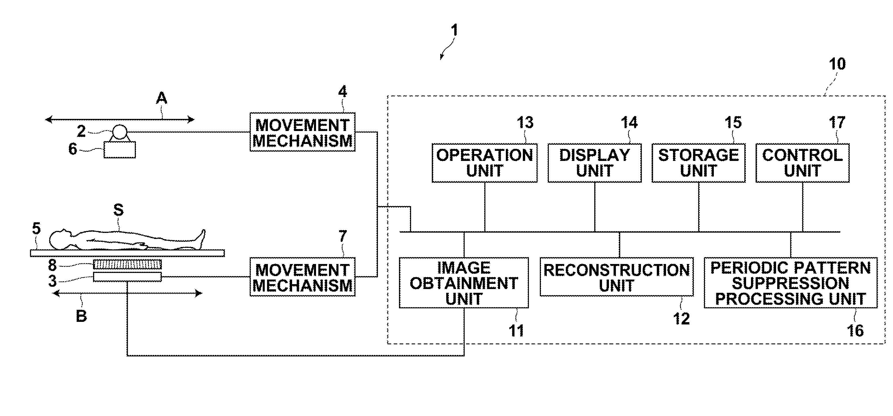
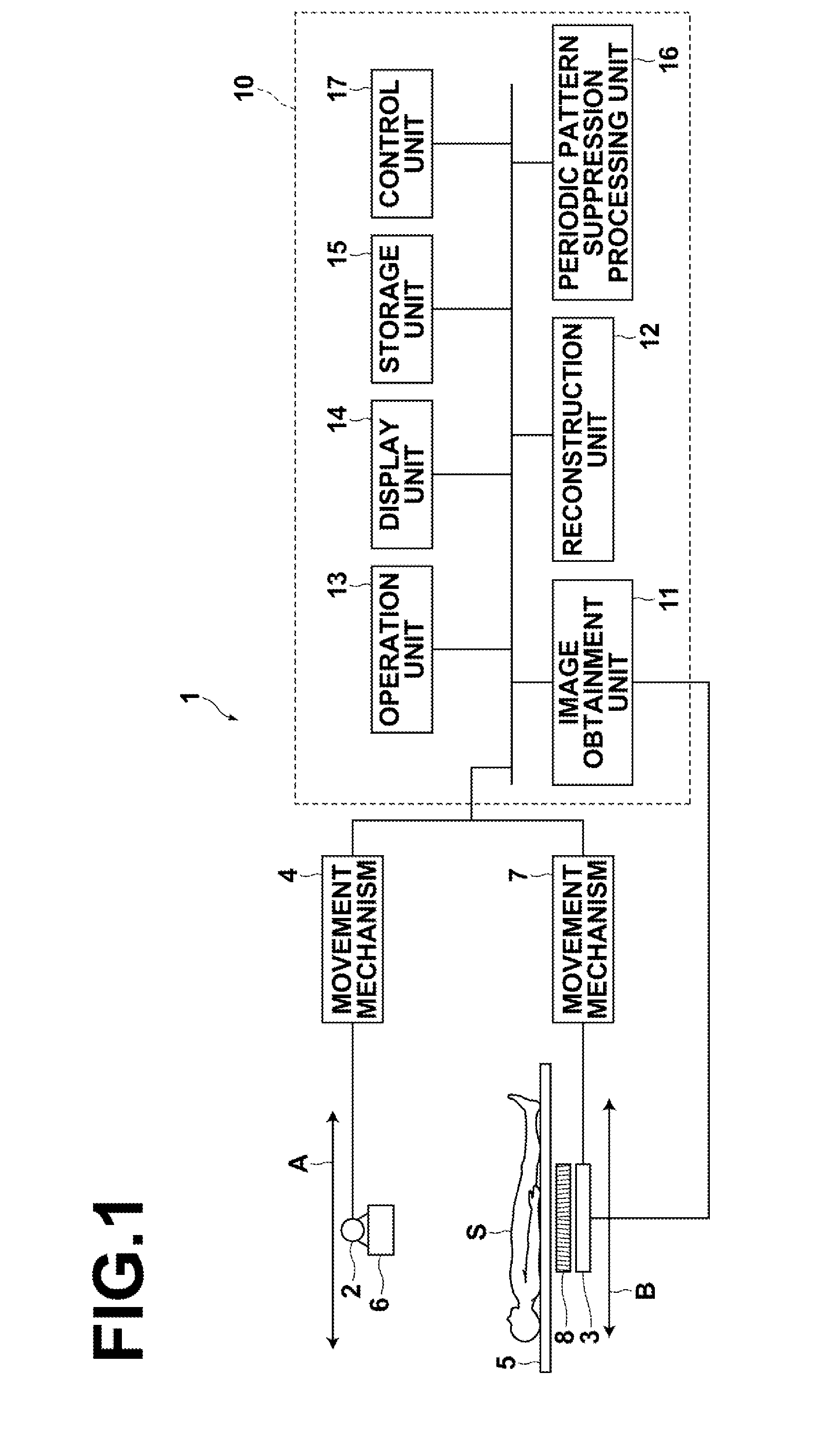
[0056]Hereinafter, embodiments of the present invention will be described with reference to drawings. FIG. 1 is a schematic block diagram illustrating the configuration of a radiographic image diagnosis system to which an image processing apparatus according to the present invention has been applied. As illustrated in FIG. 1, this radiographic image diagnosis system 1 is used to perform tomosynthesis imaging, and includes an X-ray tube 2 and a radiation detector 3. The X-ray tube 2 is moved, along a straight line or an arc, by a movement mechanism 4, and irradiates subject S on a top plate 5 of a radiography table with X-rays at plural positions on its movement path. In the embodiment of the present invention, the X-ray tube 2 is assumed to be moved along a straight line in the direction of arrow A.

[0057]Further, a collimator (a diaphragm for limiting an irradiation field) 6 is connected to the X-ray tube 2, and an operator can set a range (an irradiation range) of X-rays irradiatin...

second embodiment

[0090]Next, processing performed in the second embodiment will be described. FIG. 15 is a flow chart illustrating processing performed in the embodiment of the present invention. First, the image obtainment unit 11 obtains plural radiographic images by performing tomosynthesis imaging based on an instruction from the operation unit 13, and stores the plural radiographic images in the storage unit 15 (step ST11). Then, in the periodic pattern suppression processing unit 16, the frequency analysis unit 130 obtains frequency characteristic C0 of the periodic pattern in reference radiographic image B1 by performing frequency analysis on reference radiographic image B1 of the plural radiographic images (step ST12).

[0091]Then, the suppression unit 132 generates, based on obtained frequency characteristic C0, filters for reference radiographic image B1 and each of other radiographic images Bi to extract frequency components corresponding to the periodic patterns caused by the grid (step ST...


PUM


Abstract

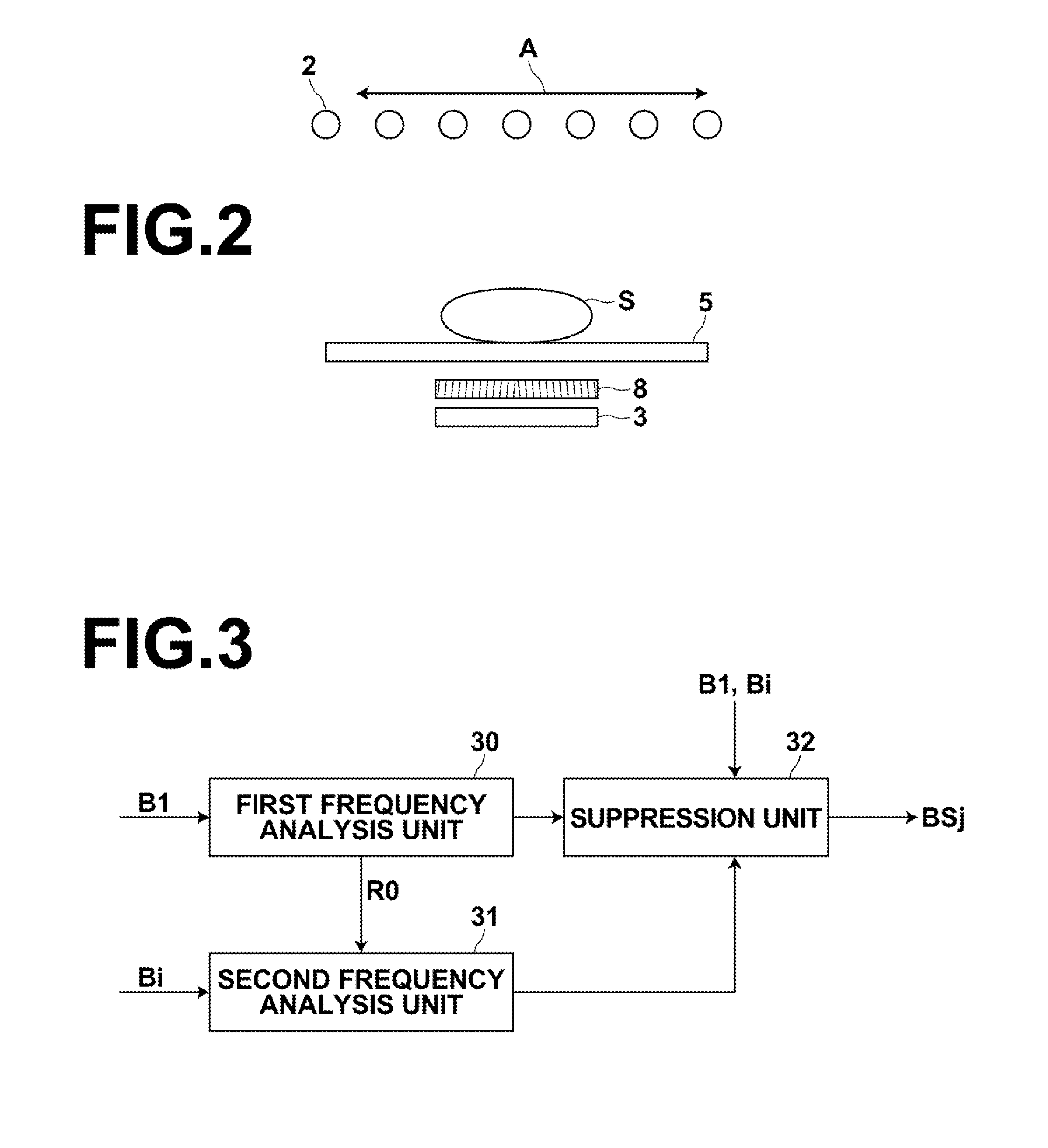
A first frequency analysis unit performs frequency analysis on a reference radiographic image of plural radiographic images obtained by tomosynthesis imaging using a grid, and obtains a frequency characteristic of a periodic pattern caused by the grid and a frequency analysis result. A second frequency analysis unit performs, based on the frequency analysis result, limited frequency analysis on a radiographic image or images other than the reference radiographic image, and obtains a frequency characteristic of the periodic pattern about the radiographic image or images. A suppression unit performs, based on the frequency characteristic, processing for suppressing the periodic pattern in all of the radiographic images.

Description

CROSS-REFERENCE TO RELATED APPLICATIONS[0001]This application. is a Continuation. of POT International Application. No. PCT / JP2013 / 001102 filed on Feb. 26, 2013, which claims priority under 35 U.S.C. §119(a) to Japanese Patent Application No. 2012-039592 filed on Feb. 27, 2012 and Japanese Patent Application No. 2012-039593 filed on Feb. 27, 2012. Each of the above application (s) is hereby expressly incorporated by reference, in its entirety, into the present application.BACKGROUND OF THE INVENTION[0002]1. Field of the invention[0003]The present invention relates to an image processing apparatus and method for performing image processing to suppress periodic patterns included in images.[0004]2. Description of the Related Art[0005]Conventionally, various kinds of radiation detector for recording a radiographic image about a subject by irradiation with. radiation that has passed through the subject were proposed, and put to practical use in medical fields and the like. As such radiat...

Claims


Application Information

Patent Timeline
IPC IPC(8): G06T7/00G06T5/00
CPCG06T7/0012G06T2207/10116G06T2207/30004G06T5/002A61B6/4291A61B6/5205G06T5/10A61B6/5252A61B6/025G06T5/70
Inventor IMAI, YOSHIRO
Owner FUJIFILM CORP
Learn More