Hybrid turbo charger

Inactive Publication Date: 2008-08-28
MITSUBISHI HEAVY IND LTD
View PDF13 Cites 24 Cited by
  • Summary
  • Abstract
  • Description
  • Claims
  • Application Information

AI Technical Summary

Benefits of technology

[0007]The present invention takes the above circumstances into consideration, and its object is to provide a hybrid turbocharger that allows easy and quick attachment/remova

Problems solved by technology

As a result, in the case of a need for carrying out an overhaul of the turbocharger, such as where a compressor impeller is removed from the rotating shafts of the turbine and the compressor, there is a p

Method used


Image

  • Hybrid turbo charger
  • Hybrid turbo charger
  • Hybrid turbo charger

Examples


Embodiment Construction

[0021]Hereunder, an embodiment of a hybrid turbocharger according to the present invention is described, with reference to the drawings.

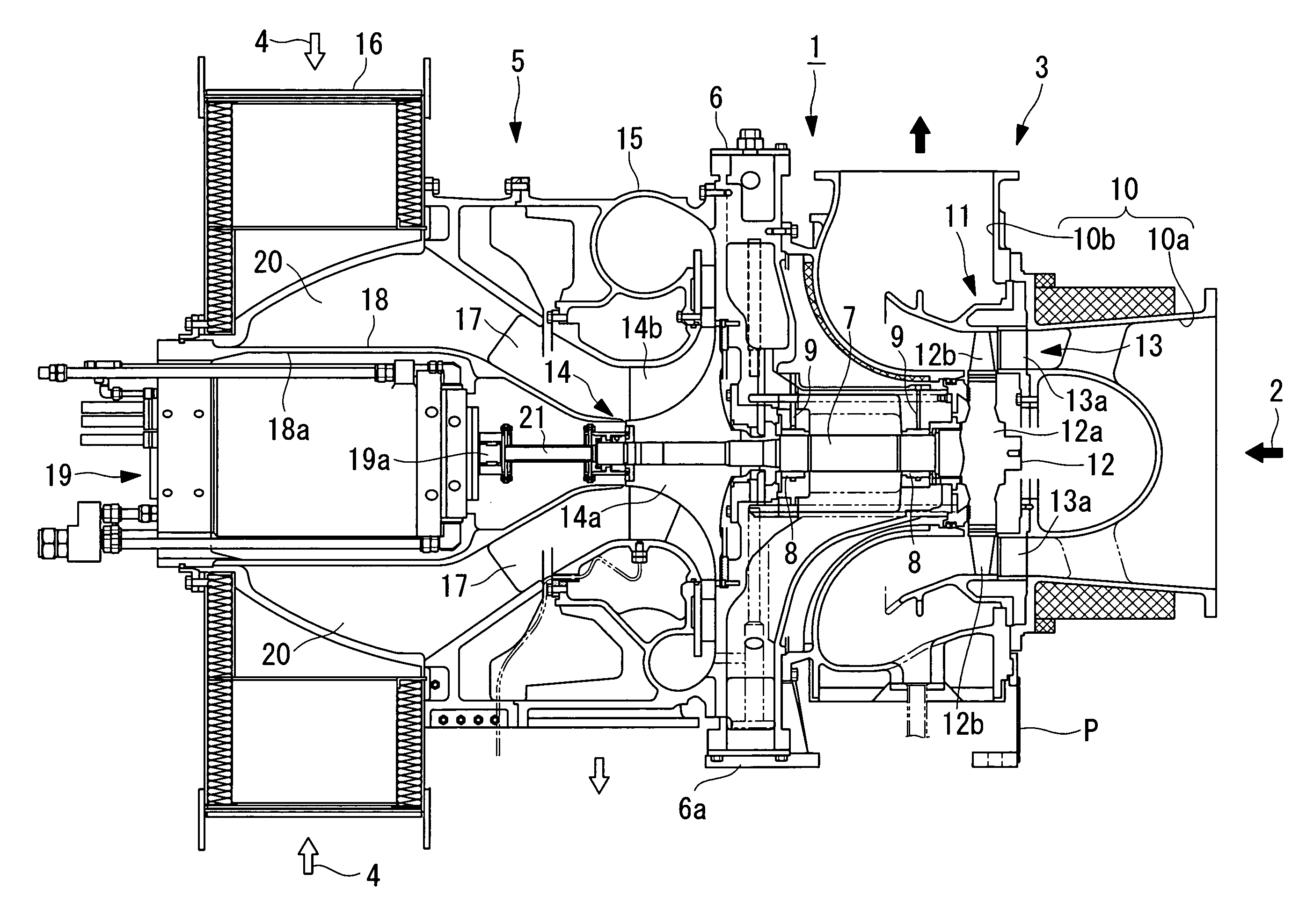
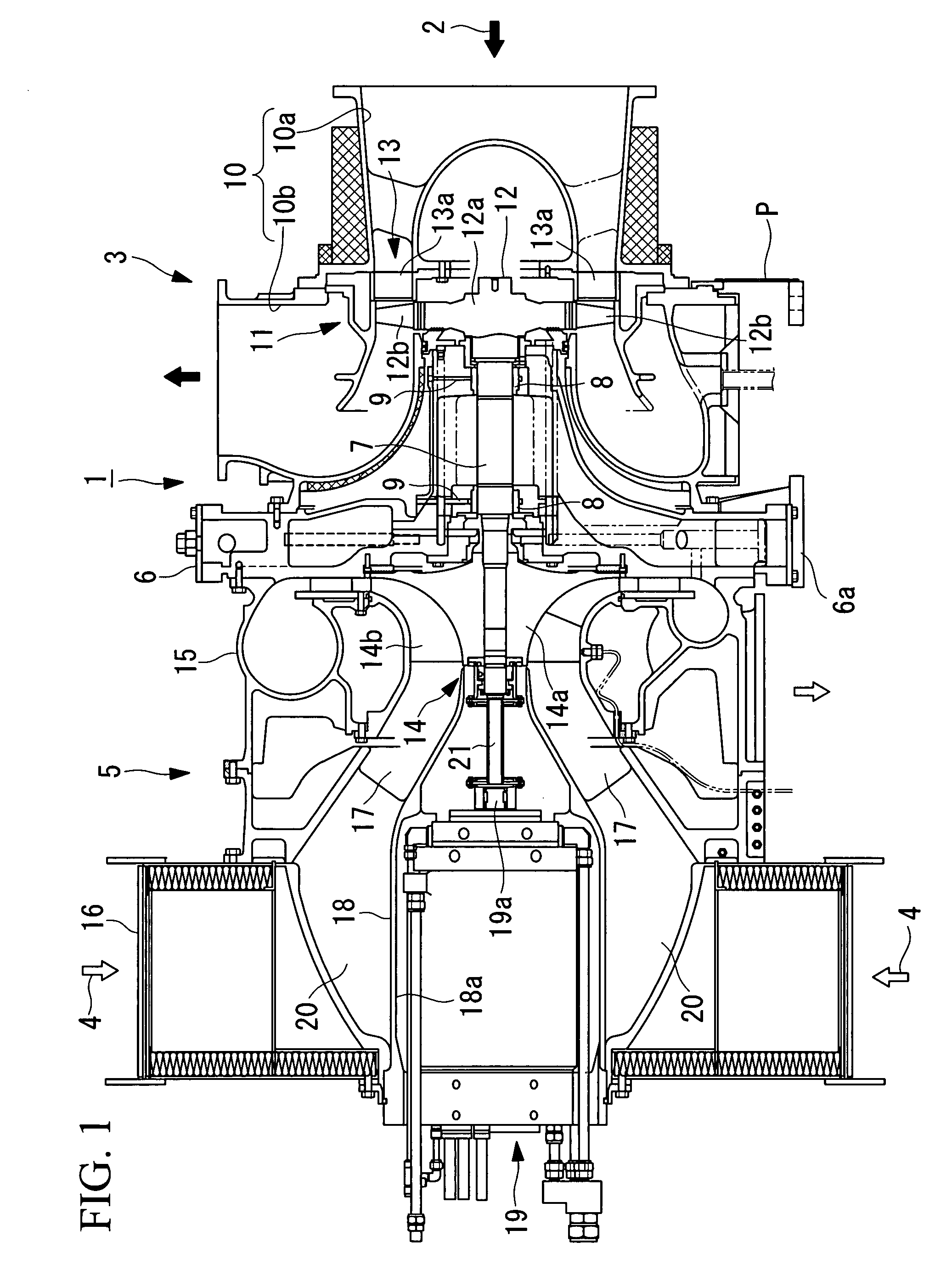
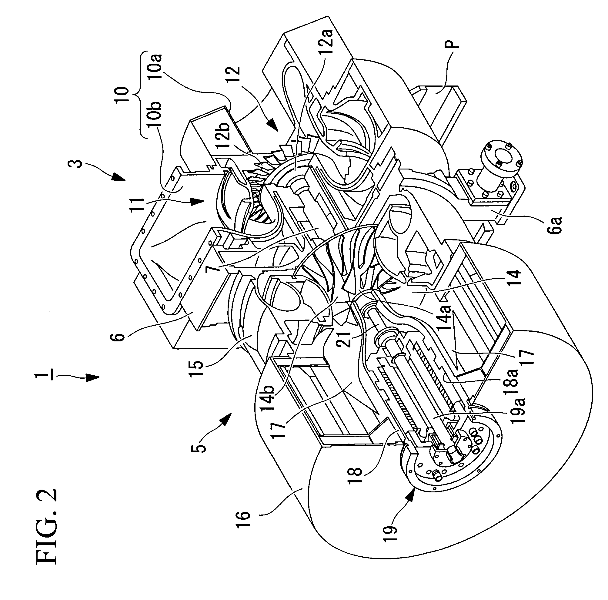
[0022]As shown in FIG. 1 and FIG. 2, a hybrid turbocharger 1 according to the present embodiment comprises main components namely: a turbine section 3 driven by exhaust gas (combustion gas) 2 introduced from an internal combustion engine (not shown in the drawing) (for example, a diesel engine or a gas turbine engine); a compressor section 5 driven by the turbine section 3 so as to pressure-feed outside air 4 into the internal combustion engine; a casing 6 provided between the turbine section 3 and the compressor section 5 so as to support them; and a power generator 19 having a rotating shaft 19a connected to a rotating shaft 7 of the turbine section 3 and the compressor section 5.

[0023]Into the casing 6, there is inserted the rotating shaft 7, one end of which projects out to the turbine section 3 side and the other end of which projects out to th...


PUM


Abstract

There is provided a hybrid turbocharger that allows easy and quick attachment/removal of a coupling attachment boss to which an end section of a coupling is attached, thereby reducing the amount of operation time required for an overhaul of the turbocharger. The hybrid turbocharger includes: a turbine section that is driven by exhaust gas introduced from an internal combustion engine; a compressor section that is driven by the turbine section to pressure-feed outside air into the internal combustion engine; and a power generator having a rotating shaft coupled to a rotating shaft of the turbine section and the compressor section via a coupling. A coupling attachment boss to which one end section of the coupling is coupled, intervenes and is fixed, via a boss fixing nut that screws onto a screw section formed on a tip end of one end section of the rotating shaft of the turbine section and the compressor section, between one end surface of a turbine rotor that constitutes the turbine section or one end surface of a compressor impeller that constitutes the compressor section, and the boss fixing nut.

Description

BACKGROUND OF THE INVENTION[0001]1. Field of the Invention[0002]The present invention relates to a hybrid turbocharger, in particular, to a hybrid turbocharger to be installed in a shipboard internal combustion engine, an internal combustion engine for a land power generator, and so forth.[0003]This application is based on Japanese Patent Application No. 2007-044027, the content of which is incorporated herein by reference.[0004]2. Description of Related Art[0005]As such a hybrid turbocharger, one equipped with a power generator, a rotating shaft of which is coupled to a rotating shaft of a turbine and a compressor of a turbocharger, is known (for example, Japanese Unexamined Patent Application, Publication No. 2004-346803).[0006]There is a hybrid turbocharger having such a configuration, in which the rotating shaft of the turbine and the compressor is coupled to the rotating shaft of the power generator via a coupling. Moreover, for example, one end section of this coupling is coup...

Claims


Application Information

Patent Timeline
IPC IPC(8): F01D15/10
CPCF01D5/026F01D15/10F02B37/10F05D2220/40F02B39/12F02C6/12Y02T10/144F02B39/10Y02T10/12
Inventor ONO, YOSHIHISASHIRAISHI, KEIICHIAONO, YOSHITSUGU
Owner MITSUBISHI HEAVY IND LTD
Why Eureka
Try Eureka