
Hybrid turbocharger

a turbocharger and hybrid technology, applied in the direction of machines/engines, mechanical equipment, electric generator control, etc., can solve the problems of time-consuming and difficult to remove the turbocharger, and achieve the effect of reducing the amount of operation time and easy and quick attachment/removal

Inactive Publication Date: 2010-04-06
MITSUBISHI HEAVY IND LTD
View PDF19 Cites 22 Cited by
  • Summary
  • Abstract
  • Description
  • Claims
  • Application Information

AI Technical Summary

Benefits of technology

The present invention provides a hybrid turbocharger that allows for easy and quick attachment / removal of a coupling attachment boss to which an end section of the coupling is attached. This reduces the amount of operation time required for an overhaul of the turbocharger. The hybrid turbocharger includes a turbine section, a compressor section, and a power generator with a rotating shaft coupled between the turbine section and the compressor section. The coupling attachment boss fixes one end section of the coupling to the rotating shaft. The invention achieves the easy and quick fitting / removing of the coupling attachment boss and the reduction of the operation time required for an overhaul of the turbocharger. The hybrid turbocharger can be easily applied to a conventional rotating shaft and is useful in reducing the stop time of an internal combustion engine and improving its operation rate.

Problems solved by technology

As a result, in the case of a need for carrying out an overhaul of the turbocharger, such as where a compressor impeller is removed from the rotating shafts of the turbine and the compressor, there is a problem in that the second coupling attachment boss can not be easily and quickly removed from the rotating shaft of the turbine and the compressor, and hence overhaul of the turbocharger is time-consuming.

Method used


Image

  • Hybrid turbocharger
  • Hybrid turbocharger
  • Hybrid turbocharger

Examples


Embodiment Construction

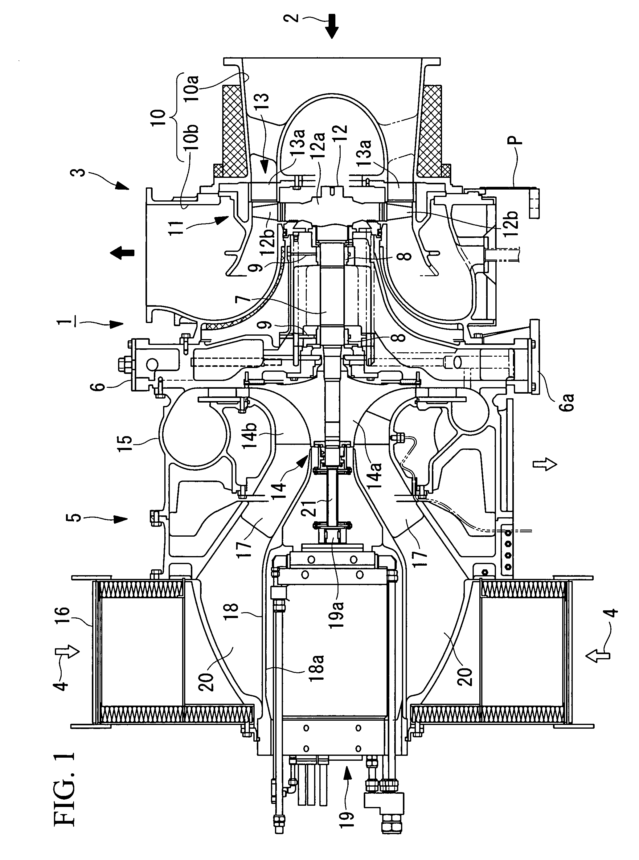
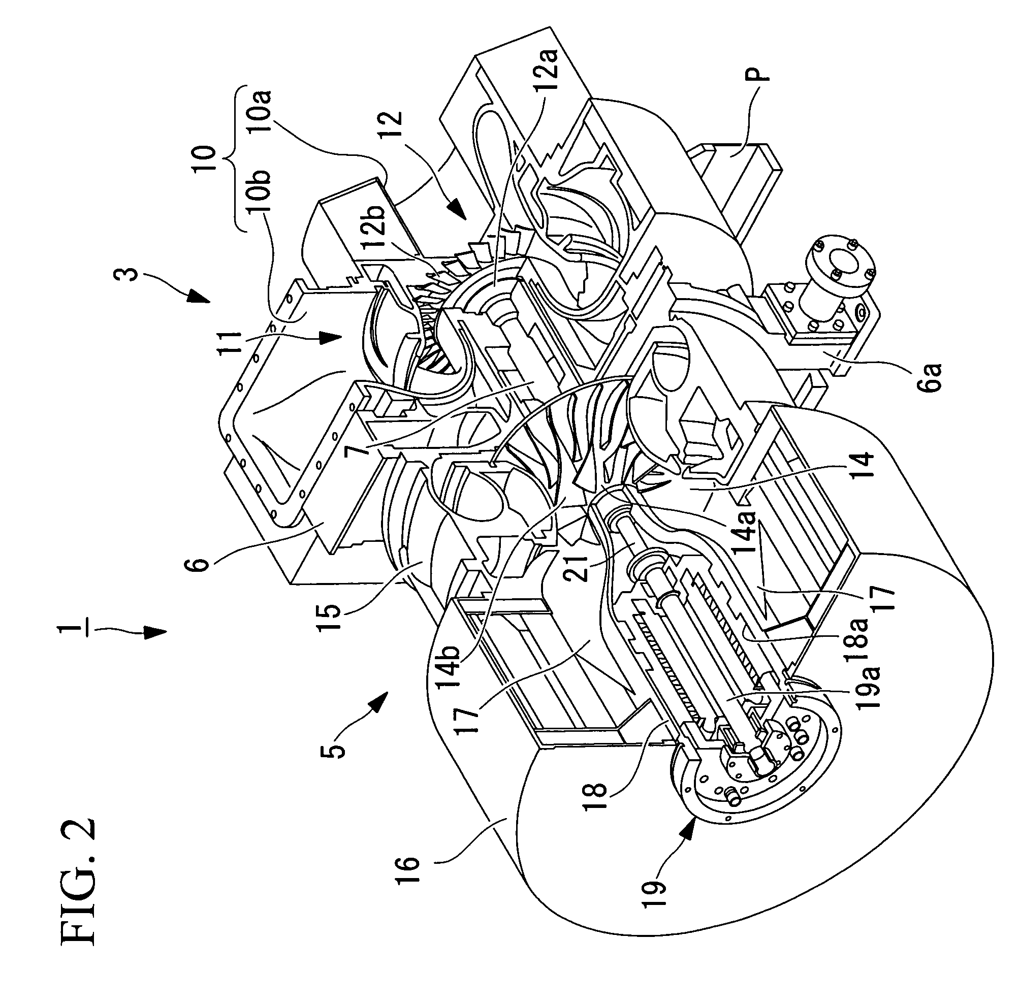
[0021]Hereunder, an embodiment of a hybrid turbocharger according to the present invention is described, with reference to the drawings.

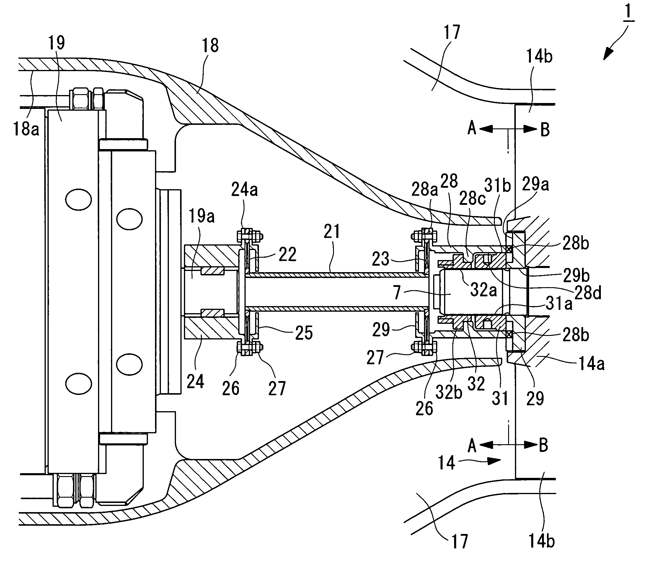
[0022]As shown in FIG. 1 and FIG. 2, a hybrid turbocharger 1 according to the present embodiment comprises main components namely: a turbine section 3 driven by exhaust gas (combustion gas) 2 introduced from an internal combustion engine (not shown in the drawing) (for example, a diesel engine or a gas turbine engine); a compressor section 5 driven by the turbine section 3 so as to pressure-feed outside air 4 into the internal combustion engine; a casing 6 provided between the turbine section 3 and the compressor section 5 so as to support them; and a power generator 19 having a rotating shaft 19a connected to a rotating shaft 7 of the turbine section 3 and the compressor section 5.

[0023]Into the casing 6, there is inserted the rotating shaft 7, one end of which projects out to the turbine section 3 side and the other end of which projects out to th...


PUM


Abstract

There is provided a hybrid turbocharger that allows easy and quick attachment / removal of a coupling attachment boss to which an end section of a coupling is attached, thereby reducing the amount of operation time required for an overhaul of the turbocharger. The hybrid turbocharger includes: a turbine section that is driven by exhaust gas introduced from an internal combustion engine; a compressor section that is driven by the turbine section to pressure-feed outside air into the internal combustion engine; and a power generator having a rotating shaft coupled to a rotating shaft of the turbine section and the compressor section via a coupling. A coupling attachment boss to which one end section of the coupling is coupled, intervenes and is fixed, via a boss fixing nut that screws onto a screw section formed on a tip end of one end section of the rotating shaft of the turbine section and the compressor section, between one end surface of a turbine rotor that constitutes the turbine section or one end surface of a compressor impeller that constitutes the compressor section, and the boss fixing nut.

Description

BACKGROUND OF THE INVENTION[0001]1. Field of the Invention[0002]The present invention relates to a hybrid turbocharger, in particular, to a hybrid turbocharger to be installed in a shipboard internal combustion engine, an internal combustion engine for a land power generator, and so forth.[0003]This application is based on Japanese Patent Application No. 2007-044027, the content of which is incorporated herein by reference.[0004]2. Description of Related Art[0005]As such a hybrid turbocharger, one equipped with a power generator, a rotating shaft of which is coupled to a rotating shaft of a turbine and a compressor of a turbocharger, is known (for example, Japanese Unexamined Patent Application, Publication No. 2004-346803).[0006]There is a hybrid turbocharger having such a configuration, in which the rotating shaft of the turbine and the compressor is coupled to the rotating shaft of the power generator via a coupling. Moreover, for example, one end section of this coupling is coup...

Claims


Application Information

Patent Timeline
Patent Type & Authority Patents(United States)
IPC IPC(8): F01D5/08F02B33/44
CPCF01D5/026F01D15/10F02B37/10F02B39/12F02C6/12F02B39/10F05D2220/40Y02T10/144Y02T10/12
Inventor ONO, YOSHIHISASHIRAISHI, KEIICHIAONO, YOSHITSUGU
Owner MITSUBISHI HEAVY IND LTD
Learn More